
Op amp F003 composition of automatic exposure timer circuit
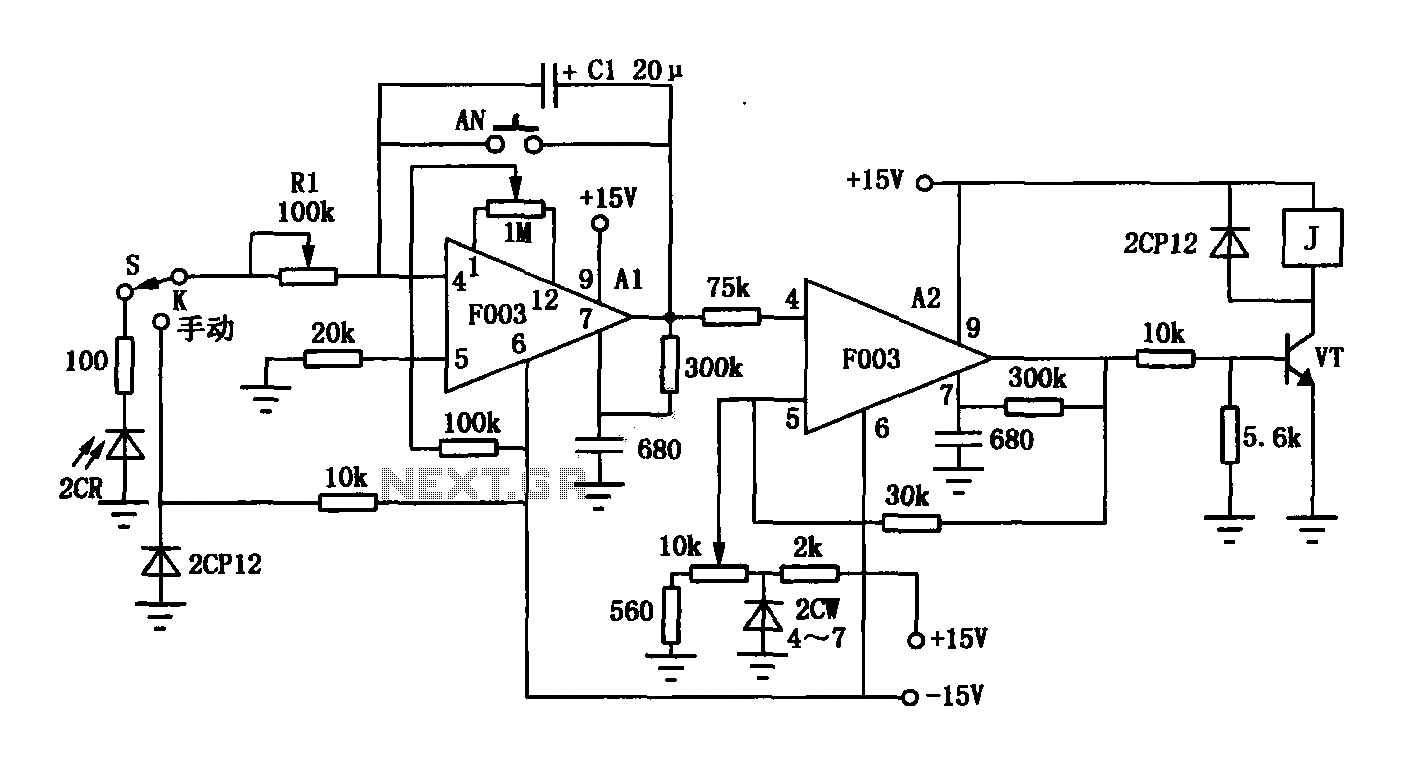
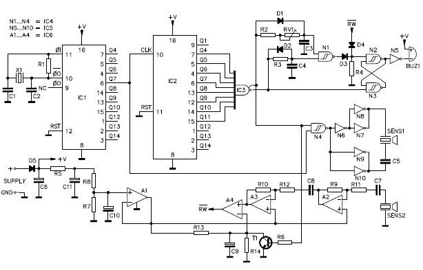
The F003 circuit is designed to provide a reliable and efficient automatic timer for photographic applications. At its core, the circuit utilizes two operational amplifiers: A1, which acts as an integrator, and A2, which functions as a comparator. The integrator (A1) accumulates the input voltage signal (V1) from the silicon photocell (2CR), which detects light levels. The output of A1 is a ramp voltage that increases over time, reflecting the cumulative light exposure.
The comparator (A2) continuously monitors the output from A1 against a predetermined threshold voltage, Ems. This threshold is adjustable via a 10k potentiometer, allowing users to customize the sensitivity of the exposure control. When the ramp voltage from A1 reaches this threshold, the comparator output transitions to a high state, signaling that the set exposure time has been reached. This transition activates transistor VT, which is configured to drive a relay. The relay can control additional loads such as lamps or cameras to stop the exposure process automatically, ensuring that the exposure is neither too short nor too long.
The circuit's design also incorporates manual control features, allowing users to bypass the automatic function if desired. A switch enables selection between automatic and manual modes, providing flexibility based on user preference or specific photographic requirements. Additionally, a reset button is included for the integrator, allowing the user to clear the accumulated charge and restart the timing process as needed.
This operational amplifier-based timer circuit exemplifies a practical application of analog electronics in photography, combining the principles of integration and comparison to achieve precise exposure control in automated systems.As shown in Figure II F003 is versatile photographic constituent operational amplifier amplifying automatic timer circuit. Operational amplifier A1 composition integrator operational amplifier A2 composed of comparators. 2CR silicon photocell voltage is generated by the integrator input signal V1, the signal input from the pin , Al output voltage with the reference voltage to the comparator comparison. When the output voltage is equal to the upper limit threshold voltage comparator Ems, A2 comparator output is high, the transistor VT conduction, relay, lamp, and the end of exposure, exposure time so as to achieve automatic control purposes.
Ems by a 10k potentiometer setting, the exposure time T = R1C1Ems / V1. S switch to automatic, manual switch. AN integrator reset button for the switch.
Related Circuits
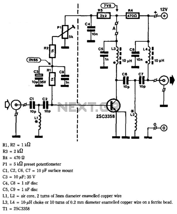
This circuit provides a gain of 10 to 15 dB from 400 to 850 MHz, making it particularly effective in scenarios where the television signal is weak. Additionally, the filters can be customized to meet individual user requirements. Construction...
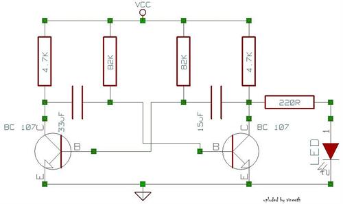
An astable multivibrator is a switching circuit that alternates its output on and off for a designated time period. This device, also known as a free-running oscillator circuit, is primarily utilized to generate square waves over a specified duration....
This is a programmable clock timer circuit that utilizes individual LEDs to signify hours and minutes. Twelve LEDs can be arranged in a circular formation to represent the 12 hours of a clock face, while an additional 12 LEDs...
A simple ultrasonic parking sonar electronic project can be designed using this schematic circuit. This ultrasonic parking sonar project features an adjustable detection range from 5 cm to 1.5 meters and a detection angle of 5 degrees. The circuit...

This circuit represents a negative resistance configuration. All previous circuits utilize RC time constants to achieve resonance. LC combinations can also be employed, providing good frequency stability, high Q factor, and rapid startup. In this circuit, a signal input...
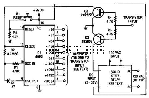
A long-duration timer can be easily constructed using a 4060 CMOS binary divider along with its integrated clock oscillator. The solid-state relay can be selected based on the specific application requirements and may be substituted with a mechanical relay...