
555 Timer Clap Switch
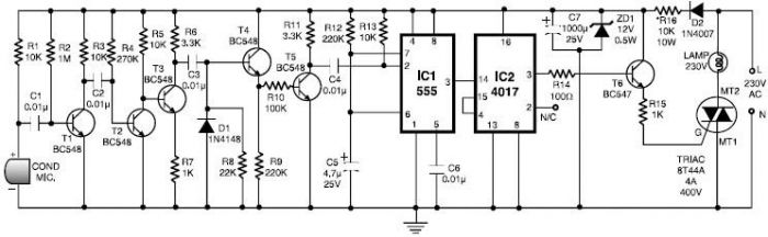
The 555 timer clap switch circuit utilizes a 555 timer IC in a monostable configuration to create a sound-activated switch. The circuit is triggered by a sound, such as a clap, which is detected by a microphone. The microphone converts the sound wave into an electrical signal, which is then amplified and fed into the trigger input of the 555 timer.
Key components of the circuit include a microphone, a preamplifier stage, the 555 timer IC, resistors, capacitors, and a relay. The microphone is typically an electret type, which requires a biasing resistor for proper operation. The amplified signal from the microphone is conditioned using a capacitor to filter out noise and ensure that only significant sound events trigger the timer.
In the monostable mode, the 555 timer produces a single output pulse when triggered. The duration of this pulse is determined by the values of the resistor and capacitor connected to the timer. When the clap sound is detected, the timer activates the relay, which can be used to control a larger load, such as a lamp or other electrical device.
The circuit can be powered by a standard DC power supply, and the output can be adjusted for sensitivity to different sound levels. Additional features may include an LED indicator to show when the circuit is active or a potentiometer to fine-tune the sensitivity of the microphone. Overall, the 555 timer clap switch circuit is a practical application of the 555 timer IC, demonstrating its versatility in sound-activated control systems.This 555 timer clap switch circuit electronic project is designed using some common electronic parts. This 555 timer clap switch circuit electronic projec.. 🔗 External reference
Related Circuits
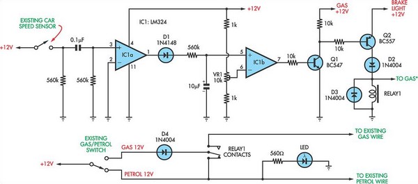
The following circuit illustrates a petrol gas switch sensor circuit diagram designed for a Pajero vehicle. It features a simple configuration utilizing the LM334 integrated circuit and operates automatically. The petrol gas switch sensor circuit is designed to monitor and...
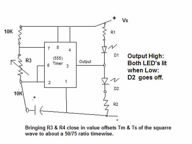
The output signal is configured to go high for approximately 0.5 seconds and then low for around 1.33 seconds. However, there is an issue present. The circuit in question likely employs a timing mechanism to achieve the specified output signal...
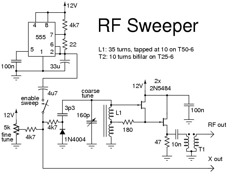
The following circuit illustrates the use of a 555 Timer IC for an RF sweeper application. Features include the utilization of a 1N4004 diode and a JF1OZL, which employs a potentiometer for precise frequency control. The circuit utilizes the 555...
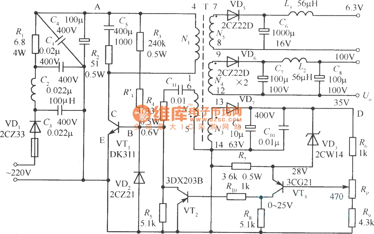
The diagram illustrates the output sampling winding of an isolated switching power supply. In the diagram, T represents a high-frequency transformer; N2 denotes the self-oscillation positive feedback winding; N3 is the error amplifier; VTS is the winding that provides...
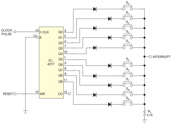
There are several methods to read multiple switch inputs using a reduced number of microcontroller unit (MCU) pins. One approach involves using an analog MCU pin to read multiple switches by assigning a unique voltage to each switch through...
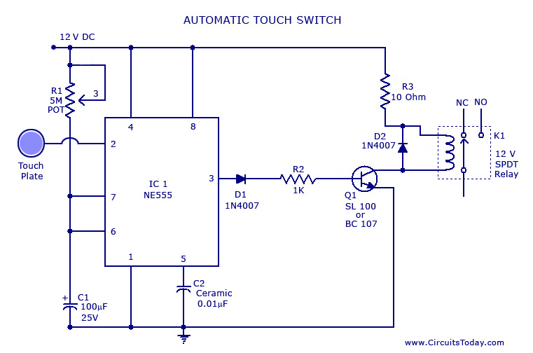
A touch switch circuit schematic utilizing a 555 integrated circuit (IC). When the touch plate is activated, a relay is switched ON for a predetermined duration, which can also be adjusted. The touch switch circuit employs a 555 timer IC...