
555 Timer Contest Entry
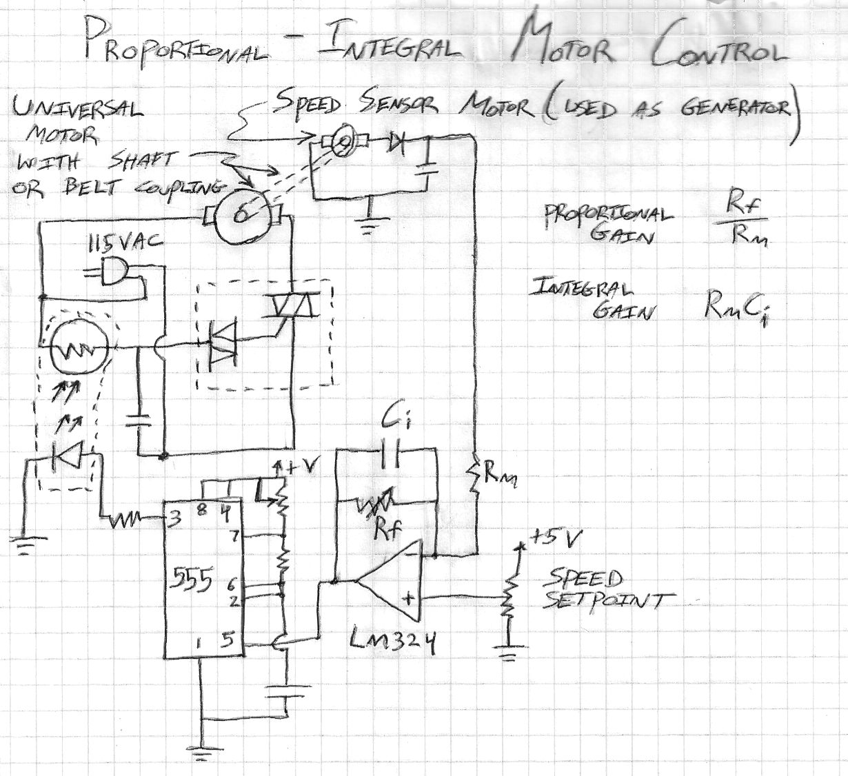
The motor speed control circuit employs a triac-diac arrangement to manage the power supplied to the motor, ensuring smooth operation without abrupt starts or stops. The triac allows for bidirectional current flow, which is essential for controlling AC motors. The diac serves as a triggering device that activates the triac once the voltage across it reaches a certain threshold, thus enabling the motor to start only when the R-C network has charged sufficiently.
The R-C network consists of a resistor and a capacitor, where the resistor's value is variable, determined by the resistance of the CdS photoresistor. This photoresistor alters its resistance based on the intensity of light it receives from the LED, which is modulated by the 555 timer. The astable multivibrator configuration of the 555 timer produces a continuous square wave output, where the duty cycle can be adjusted to control the brightness of the LED. The higher the duty cycle, the more light is emitted by the LED, leading to a lower resistance in the CdS photoresistor, which allows more current to flow through the motor.
The op-amp circuit utilizing the LM324 integrates feedback from the small motor, which operates in conjunction with the main motor. As the main motor accelerates, the small motor generates a DC voltage that reflects its speed. The op-amp compares this voltage to a user-defined reference voltage, adjusting the control signal sent to the 555 timer to maintain the desired speed. This feedback loop ensures that the motor operates at a consistent speed, compensating for variations in load or other external factors.
Overall, this motor speed control circuit is a robust solution for variable-speed applications, providing precise control over motor operation while maintaining safety and efficiency. The combination of optical coupling, feedback mechanisms, and pulse-width modulation enables effective control over AC universal motors, making it suitable for various power tools and appliances.This is a motor speed control circuit that allows safe and easy control of 115VAC "universal motors" like drill motors, blender motors, other power tools, etc. The motor is controlled directly by a triac-diac component that is found in variable-speed universal motor devices (such as electric drills.
) The component will not allow current to flow th rough the motor until the R-C network charges to a certain level. In this case the capacitance is fixed, but the resistance is determined by a CdS photoresistor. A standard LED is optically coupled to the CdS photoresistor, and the LED is controlled by a 555 astable circuit. The duty cycle of the 555 output waveform will determine the average amount of light falling on the CdS photoresistor, and thus the CdS resistance, and thus the current flowing through the motor.
For best operation, the 555 output frequency should be much higher than the mains AC frequency (ie 60 Hz). A good value for the 555 frequency would be about 5 KHz. The 555 control voltage is set by an opamp circuit (LM324) that amplifies the difference between a user-set voltage and a voltage generated by a small motor whose shaft is coupled to the main motor being controlled.
The small motor`s function is to generate a DC voltage that is proportional to shaft speed. Its value is amplified and integrated by the opamp circuit for programmatic proportional and integral control. The 555 serves as a high-current pulse driver for the LED, taking an analog control signal and allowing some control of the pulse rate and height via the R-C timing network and current-limiting resistor.
🔗 External reference
Related Circuits
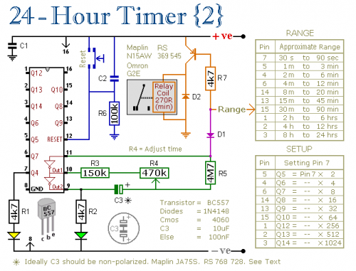
A pair of multi-range timers that provide timing periods of up to 24 hours and beyond. Both timers are fundamentally similar, with the primary distinction being that Version 1 energizes the relay when the time expires, while Version 2...
This timer was designed primarily to switch off a portable radio after a set period. This feature allows users to fall asleep on the beach or in a hammock, knowing that the receiver will automatically turn off after a...
Child lock voltage comparator 555 monostable circuit, a counter, JK flip-flop, UPS power supply design digital logic circuit, electronic door control, and various additional circuitry to ensure the safety circuit can operate with a high safety factor. The circuit...
The following circuit illustrates a repeating interval timer circuit diagram utilizing the CMOS 4060 integrated circuit (IC). Features include its foundation on the CMOS 4060 IC and a 14-bit binary counter. The CMOS 4060 IC is a versatile component widely...
A simple pulse modulator circuit can be constructed using a 555 integrated circuit (IC). The 555 chip features a special modulator input located at pin 5. Below is the schematic diagram of the circuit. The pulse modulator circuit utilizing the...
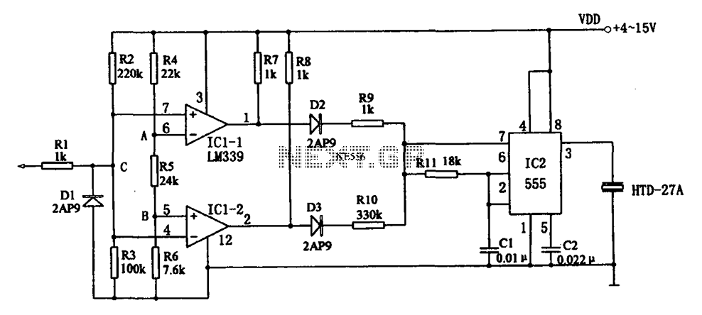
The acoustic logic level probe circuit consists of a voltage comparator, multivibrator, piezoelectric ceramics (HTD), and other components. The configuration of the audio circuit determines the frequency of the sound level to assess the logic levels of TTL or...