
555 monostable circuit trigger solenoid
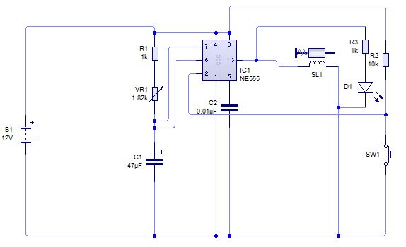
A circuit for triggering solenoid valves in a car's airbag system is being developed, focusing on a monostable 555 timer configuration. This design is intended to provide a precise timing mechanism, allowing the solenoid to actuate within a specified range of 0 to 1 second. The solenoid valves selected for this application operate at 12V and require a current of 0.5A, with the capability of achieving activation speeds up to 200 milliseconds.
The monostable 555 timer is advantageous in this application due to its ability to generate a single output pulse when triggered. In the proposed design, when the activation button is pressed, the timer will output a pulse that energizes the solenoid, deploying the airbag. The design must ensure that the output pulse duration is sufficient to activate the solenoid without exceeding the maximum operational time for the airbag deployment.
A critical aspect of the design is the inclusion of a protection diode connected in parallel with the solenoid. This diode serves to suppress back electromotive force (back EMF) generated when the solenoid is de-energized, which could otherwise damage the circuit components. The necessity of transistors in the output stage of the circuit is also discussed. Typically, a single transistor can be used to amplify the control signal from the 555 timer to drive the solenoid. The choice of transistor should be based on its current handling capability, ensuring it can operate comfortably within the 0.5A requirement.
The input lockout mechanism is another essential feature of the circuit. A capacitor can be employed to couple the activation switch to the input of the timer, effectively filtering out noise and preventing false triggering. This capacitor, in conjunction with a pull-up resistor, will maintain the input state when the switch is not engaged. Additionally, a protection diode can be placed from the trigger input to the positive supply voltage to safeguard against voltage spikes.
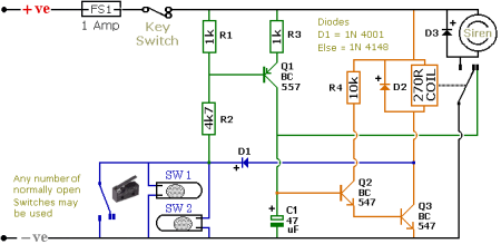
Given that airbags are typically single-use devices, the design must account for the possibility of re-triggering the solenoid after deployment. In this project, however, a reusable airbag system is being simulated, allowing for multiple deployments. To mitigate the risk of inadvertently activating the solenoid a second time, a dual-switch mechanism may be implemented. This would involve one switch to "arm" the circuit and a separate switch to "fire" the solenoid, ensuring that accidental activations are minimized.
In summary, the proposed circuit design for triggering solenoid valves in a reusable airbag system employs a monostable 555 timer, with necessary protective components to ensure reliable operation. The design considerations surrounding the use of transistors, input lockout mechanisms, and activation controls are crucial for the successful implementation of this system.Well i posted a similar circuit in another topic but a lot has changed in the design. So here is a brief story of what i am doing, actually i am in a project where i have to design a circuit which can be used to trigger solenoid valves for the airbags in the car, so i need a circuit with a time range of 0 to 1 seconds. Also the valves chosen are 1 2 V, 0. 5 A and can go up to the maximum speed of 200 milisecond. In my group meeting it was decided to use a monostable 555 circuit to trigger valves as they need some sort of time regulation because it is something like that you press a button and an airbag go will off instantly and that car would be a demonstrator only! so i am a little confused as can there be an alternative to the circuit above as it looks too complicated I know i will need a diode connected in parallel to solenoid to prevent back emf but exactly don`t understand why are transistors required if transistors are required then what type of transistors do I use This circuit will require probably only one transistor on the output, with a couple resistors.
That should drive your solenoid which you said was 0. 5 amp right The input lockout can be as simple as a capacitor that couples the switch to the input, with a pullup resistor, and a protection diode from trigger to the positive supply voltage. Why Airbags are use-once-only things. In an accident there would only be a single trigger. Besides, surely it won`t matter if the valve opens repeatedly after the bag has deployed If this is a hypothetical system, e.
g. for a school project, then fine. If it`s for a real-life airbag system then a lot more needs to be done to prevent any possibility of false triggering, e. g. by voltage spikes on the 12V supply. so in this simulator we will use airbags made of another material which can be reused again and again!
its going to be like this once an airbag has gone off it will be repacked into its casing then you press the button, it will go off again! This circuit will require probably only one transistor on the output, with a couple resistors. That should drive your solenoid which you said was 0. 5 amp right The input lockout can be as simple as a capacitor that couples the switch to the input, with a pullup resistor, and a protection diode from trigger to the positive supply voltage.
I was assuming that when the 555 fires it energizes the valve coil and that shoots air into the bag for say 200ms. But if they 555 fired again it would shoot more air into the bag possibly damaging it, or is that not a problem I`m also asking about this in another thread.
What we need to know is how critical a second firing would be. Would it hurt to fire it again later by accident Maybe the only way is with two switches. one to "arm" the circuit and one to actually "fire" the circuit. It looks like the circuit posted by alec in post #11 should do it. Since the timer doesnt have to produce a really really short pulse, the capacitor coupling should be ok, and combined with the latch on the input that will lock out future mis-triggers. We should really do something like that for this application so there is absolutely no chance of unwanted triggering.
🔗 External reference
Related Circuits

This universal power supply includes a bridge rectifier, a voltage stabilizer (78xx), and a PNP power transistor. This combination allows for a load current output. The universal power supply circuit is designed to convert alternating current (AC) from the mains...
The schematic illustrates a Simple Motorcycle Alarm Circuit Diagram created by Ron J. It incorporates micro-switches to safeguard removable panels and... The Simple Motorcycle Alarm Circuit Diagram is designed to enhance the security of motorcycles by utilizing a series of...
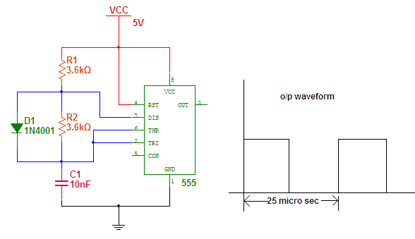
The IC555 is an on-chip multivibrator that allows the design of astable, monostable, and bistable multivibrators. Its primary applications include generating timing signals, clock waveforms, synchronizing signals, and square wave oscillators, among others. This document will discuss various applications...
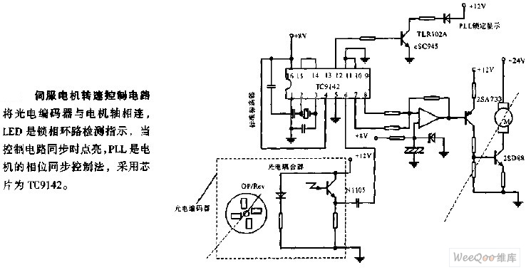
The servo motor speed control circuit connects the photoelectric encoder to the motor shaft. The LED serves as an indicator light for the phase-locked loop (PLL) detection, illuminating when the control circuit is synchronized. The PLL employs a phase...
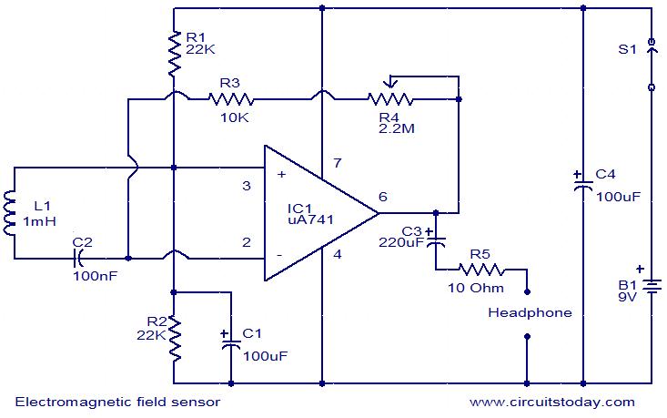
The following circuit illustrates an Electromagnetic Field Sensor Circuit Diagram. This circuit is based on the uA741 integrated circuit. Features: it is used to sense electromagnetic fields. The Electromagnetic Field Sensor Circuit utilizes the uA741 operational amplifier to detect variations...

A PoE Plus power level of 30 W can be achieved by utilizing an external MOSFET along with a controller that is compatible with the older standard. Power over Ethernet (PoE) technology enables the delivery of electrical power along with...