
Time Delay Relay Circuit with 555
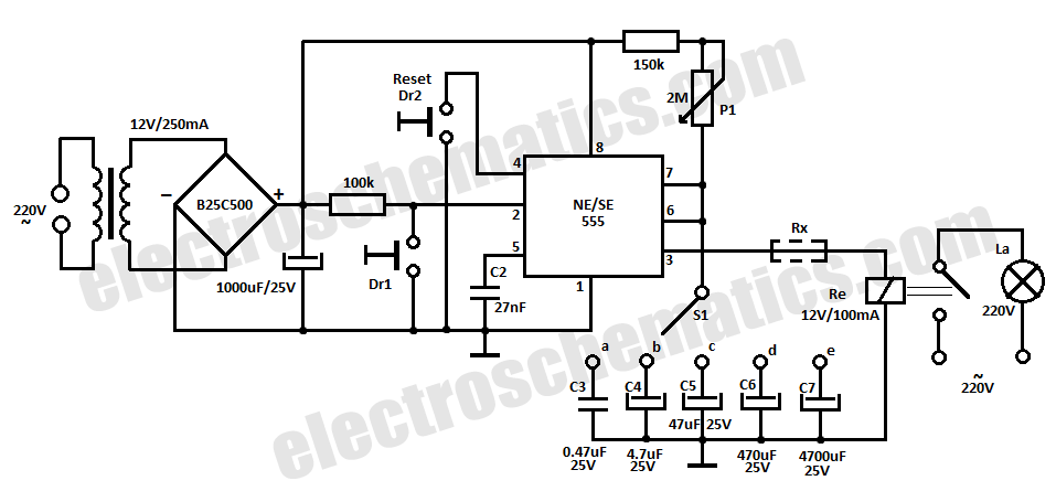
The NE/SE555 integrated circuit is a versatile timer used in various applications, including time delay relays. In this circuit, the IC operates in monostable mode, where it generates a single output pulse in response to an input trigger. The duration of this pulse, which corresponds to the time delay before the relay activates, is determined by an external resistor and capacitor connected to the 555 timer.
To set the time delay, a resistor (R) and a capacitor (C) are selected according to the formula: T = 1.1 * R * C, where T is the time delay in seconds. The resistor can be a variable resistor (potentiometer) to allow for adjustable delays, while the capacitor is typically an electrolytic capacitor to store the charge necessary for timing.
The input trigger can be activated by a momentary switch or a sensor output, providing a low voltage signal to the 555 timer. Upon receiving this trigger, the timer activates the output pin, which in turn energizes the relay coil. This relay can control higher voltage loads, making it suitable for applications such as lighting control, motor activation, or other devices requiring a time delay before activation.
The circuit's design must also consider the power supply voltage, which typically ranges from 4.5V to 15V for the NE/SE555. Proper decoupling capacitors should be placed near the power supply pins of the IC to ensure stable operation and minimize noise. Additionally, if the circuit is expected to operate in varying temperature conditions, the choice of components, particularly the timing capacitor and resistor, should be made with temperature stability in mind to maintain consistent timing performance.
Overall, this time delay relay circuit utilizing the NE/SE555 timer is a reliable solution for applications requiring precise timing control, with the added benefit of temperature stability.This time delay relay circuit is built with IC NE/SE555, produced by Intersil which contains a precision timer. Stability to temperature variations is 0.00.. 🔗 External reference
Related Circuits
This simple circuit combines two or more audio channels into a single channel (for example, converting stereo to mono). The circuit is capable of mixing any number of channels and operates with minimal power consumption. While the schematic illustrates...
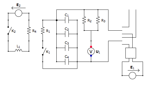
This is the discharging circuit. The red lines indicate the flow of energy from the capacitors to the terminals when the switch is in the upward position. The circuit is complete due to the connection of the terminals by...
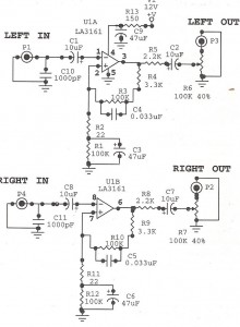
Preamplifiers are utilized to amplify low-level signals, such as those from microphones and tape heads, before they are sent to power amplifiers. Power amplifiers typically exhibit lower sensitivity. The frequency response can also be adjusted and optimized at the...
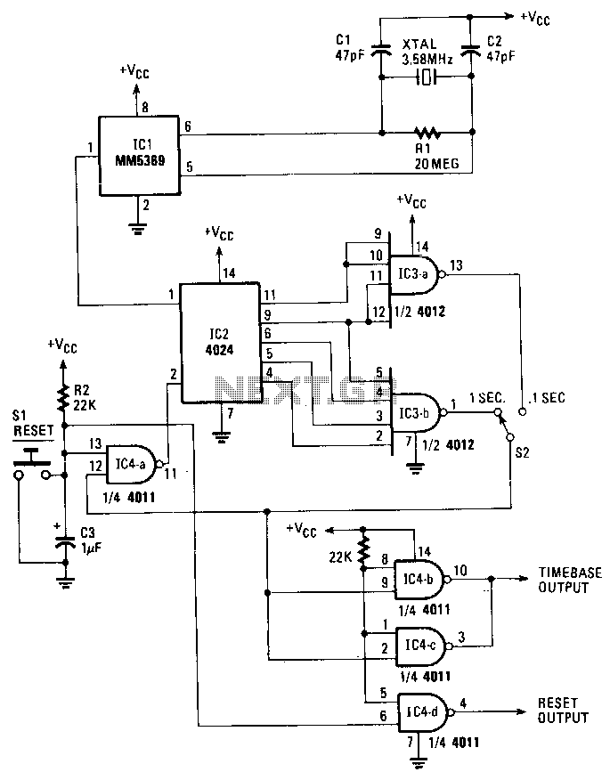
An on-board oscillator and a 17-stage divider comprise IC1. By connecting a standard 3.58-MHz television color-burst crystal as illustrated, a precise source of 60-Hz square waves is generated at the output of IC1, pin 1. These pulses are subsequently...
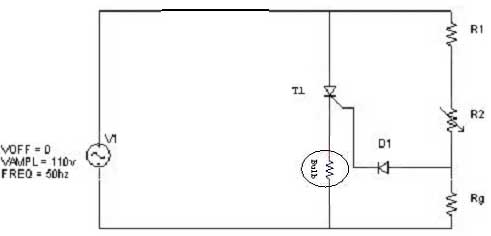
Simple resistor and diode combinations are used to trigger and control silicon-controlled rectifiers (SCRs) across the full 180-degree electrical range, exhibiting reliable performance at commercial temperatures. These circuits function optimally when SCRs possess relatively high gate sensitivities. In this...
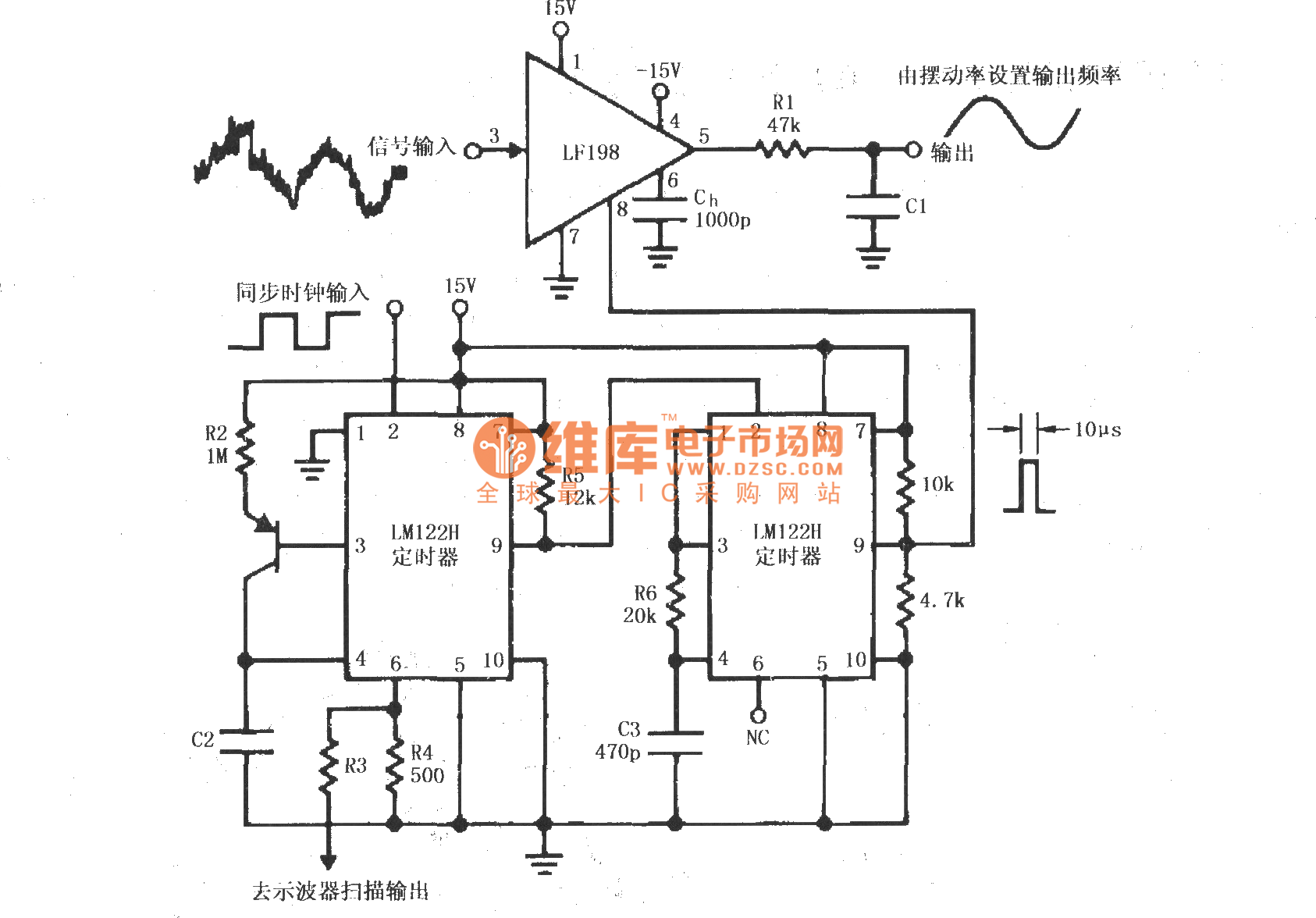
A synchronous clock signal is fed into a cascade of timer circuits composed of two LM122H devices. The synchronization clock is then converted into a pulse of the desired width, which is added to the LF198 logic end (pin...