
Mini Voice Operated Relay circuit diagram
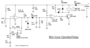
The voice-operated relay circuit is designed to respond to sound inputs, activating a relay that controls a connected load. The core components of this circuit typically include a microphone for sound detection, an amplifier to enhance the microphone's signal, and a relay driver circuit that switches the relay on and off based on the amplified sound signal.
The microphone captures sound waves, converting them into an electrical signal. This signal is then amplified to ensure that even quiet sounds can trigger the relay. The amplifier may consist of operational amplifiers configured in a non-inverting arrangement to boost the microphone's output. The gain of the amplifier can be adjusted to suit the environment's noise level.
The relay driver stage is crucial for controlling the relay. It often includes a transistor that acts as a switch, turning on when the amplified sound signal exceeds a certain threshold. This threshold can be set using a variable resistor or potentiometer, allowing for customization based on the specific application or environment.
The timing circuit, which includes components C2 and R5, determines how long the relay remains activated after the sound input ceases. By increasing the capacitance of C2 and adjusting R5, the delay can be tailored to meet the requirements of the user. The choice of a potentiometer or trimpot for R5 facilitates easy adjustments without the need for soldering, making it user-friendly.
The relay itself is rated for the voltage and current of the load it will control. It is essential to choose a relay that can handle the electrical specifications of the connected device to ensure safe and reliable operation. The output from the relay can be used to control various devices, such as lights, fans, or other electrical appliances.
Overall, this voice-operated relay circuit provides a versatile solution for sound-activated control, with adjustable timing and sensitivity features that enhance its usability in different applications. Proper design considerations, including component selection and layout on the PCB, will ensure optimal performance and reliability of the circuit.This is the circuit diagram of a voice operated relay. It similar with sound activation switch circuit which will turn on and turn off (connect and disconnect) the switch depending on the sound input. The output switch of this circuit is act by a relay. You could change the release time constant (C2 & R5) to say 30 seconds and use the VOX as a lig ht switch with this delay time before turning off. Increase C2 to say 10uF and R3 to 3M3. To make the easy adjustment, you may use potensiometer or trimpot to varying the value of resistor. You will need additional place on the PCB but it will easier for you to make some adjustment 🔗 External reference
Related Circuits
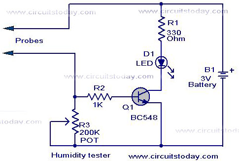
A simple humidity tester circuit using only an LED, a transistor, and a few resistors is explained with a clear circuit schematic. The humidity tester circuit is designed to provide a visual indication of humidity levels using basic electronic components....
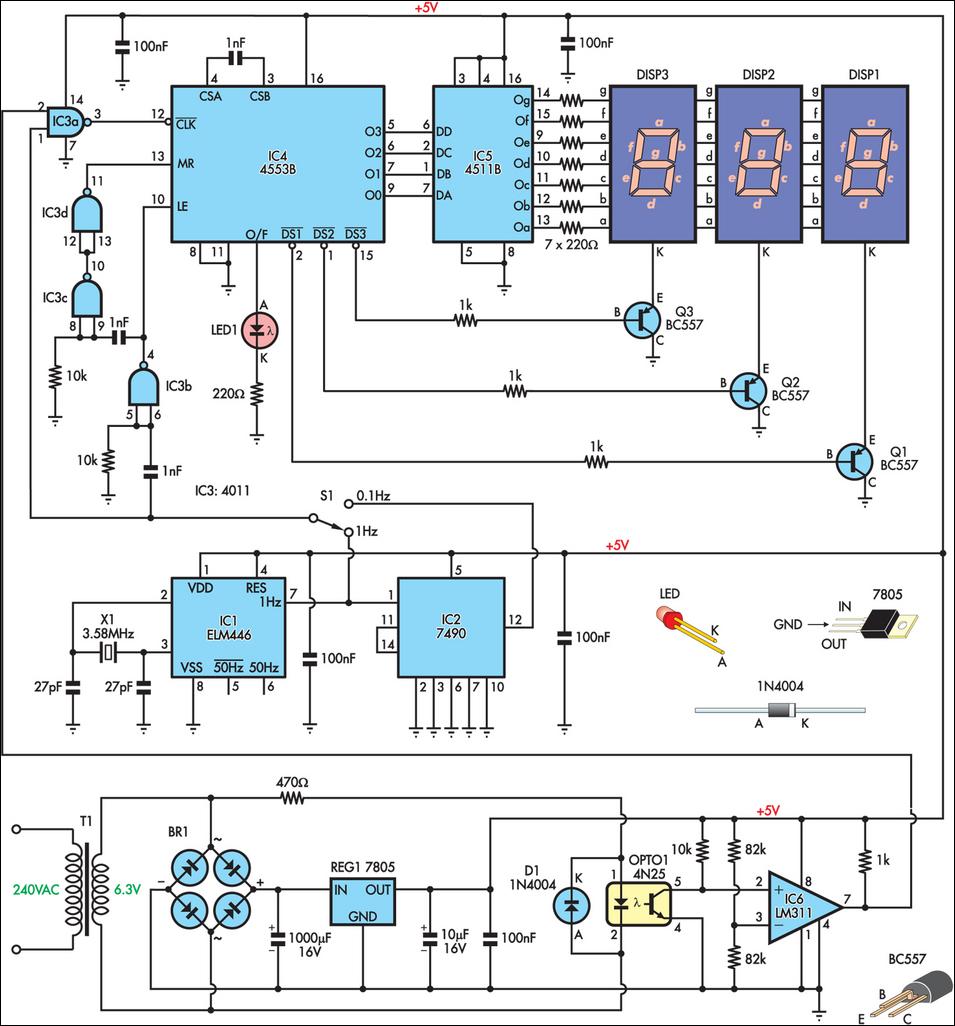
This is a simple frequency counter designed to monitor the 240VAC mains supply. It has a frequency range of 0-999Hz, making it suitable for use with 400Hz equipment as well. Standard TTL/CMOS logic is utilized for the counters and...
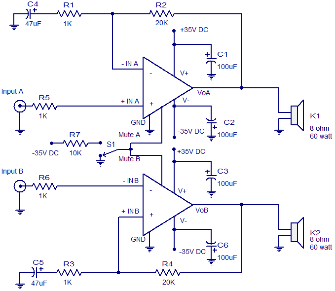
The circuit diagram presented is for a 2 x 60 Watt stereo amplifier utilizing the LM4780 from National Semiconductors. The LM4780 is an excellent audio amplifier integrated circuit capable of delivering 60W RMS power output per channel into 8-ohm...
This document outlines the theory behind a high-speed control scheme for an LED display screen circuit. The circuit utilizes the MCS51 series microcontroller to manage the LED display. A 62512 random access memory (RAM) is employed for data storage,...
The following circuit illustrates the sensor circuit diagram for automatic room lights. This circuit is based on the CD4017 integrated circuit (IC) and features the use of two light-dependent resistors (LDRs). The automatic room light circuit utilizes the CD4017 decade...
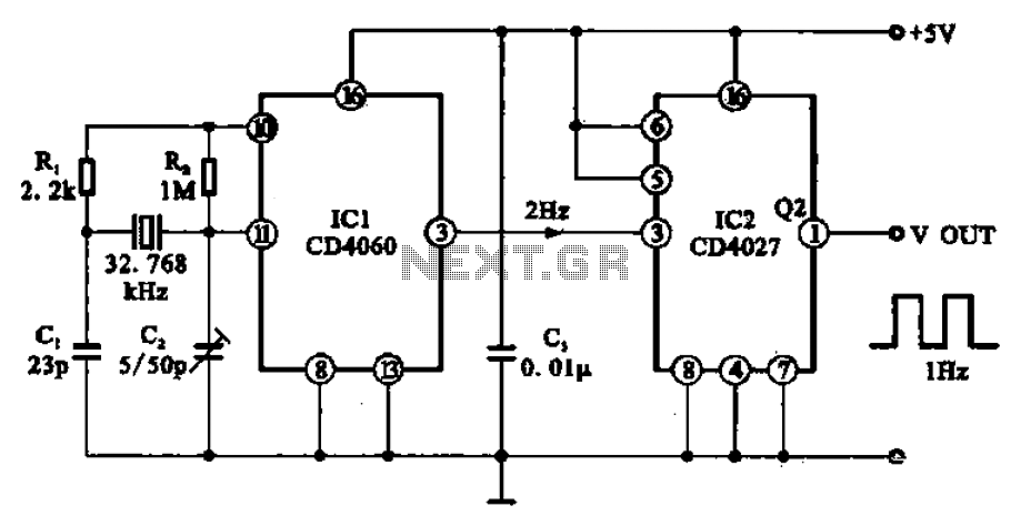
A 1Hz clock signal generator circuit is presented, which demonstrates a sophisticated clock signal generating mechanism. This circuit can be utilized for digital clocks and timing applications. It comprises a binary counter (CD4060), a JK flip-flop (CD4027), and a...