
TDA7360 Stereo Test and ApplicationCircuit and Datasheet
The TDA7360 is designed for automotive audio applications, providing robust performance in both bridge and stereo modes. It is capable of delivering high-quality audio output, making it suitable for integration into car radio systems. The amplifier's architecture allows for efficient power management, ensuring minimal heat generation while maintaining sound fidelity.
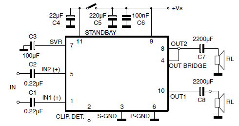
The circuit schematic typically includes input and output connections, power supply pins, and additional components that support the amplifier's operation. For instance, the input decoupling capacitor (C1) plays a crucial role in filtering out noise and stabilizing the input signal, thereby enhancing audio clarity. Other components may include resistors for gain adjustment, additional capacitors for power supply stabilization, and a clipping detector circuit that provides feedback on the amplifier's output performance, preventing distortion during operation.
When designing a circuit using the TDA7360, it is essential to adhere to the recommended values for external components to ensure optimal performance. This includes selecting capacitors and resistors with appropriate voltage ratings and tolerances. The layout of the circuit board should also be considered, as proper grounding and component placement can significantly affect the amplifier's efficiency and audio quality.
In summary, the TDA7360 Class AB Audio Power Amplifier is a versatile and efficient solution for car radio applications, providing high output power and excellent audio performance with minimal external components. Careful consideration of the circuit design and component selection is vital for achieving the best results in automotive audio systems.Car radio application using class AB Audio Power Amplifier usually has TDA7360 inside it. It is a22W bridge or stereo audio ampwith features such as minimum external components, high output power, fixed gain, clipping detector and etc. Above circuit diagram shows thisTDA7360 stereo test and application circuit schematic. Value recommendation of ea ch external components of this circuit can be described as follows:1. C1 for input decoupling (CH1) is 0. 22 uF 🔗 External reference
Related Circuits
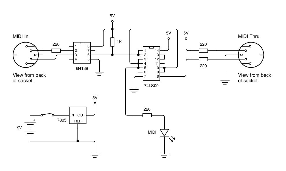
MIDI data is transmitted between instruments using a current loop, and an opto-isolator (6N139) is employed to convert this current loop into TTL pulses. The circuit utilizes the 6N139 opto-isolator to separate the MIDI signal from the receiving device, ensuring...
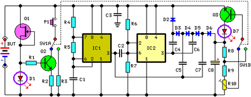
FET Q1 functions as a constant current generator, providing biasing for LED D1 and the base of Q2. This configuration ensures that D1 emits light at a consistent intensity, regardless of the battery voltage, which ranges from 3 to...

Before using LEDs, it is advisable to test them. An LED tester allows for testing even in low light conditions. LEDs are available in various shapes and colors, with some featuring clear, colorless packages and others having colored plastic...
This small circuit is designed to verify the basic functionality of an infrared remote control unit. The circuit utilizes a straightforward approach by connecting a piezo buzzer directly to an IR receiver integrated circuit (IC). This configuration is as...
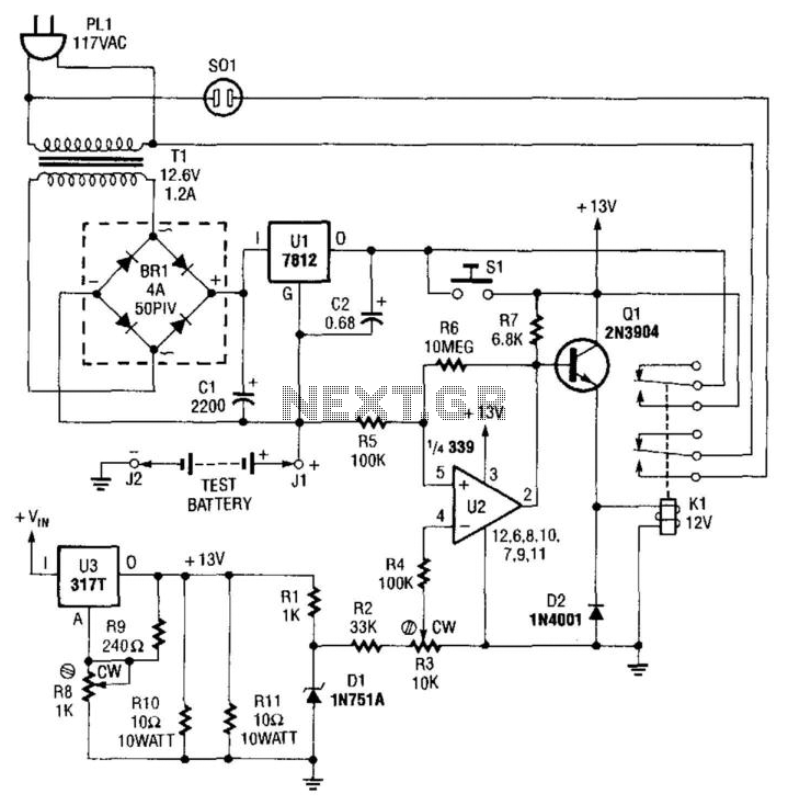
This NiCad battery tester discharges the test battery at a rate of 500 mA. When the endpoint of 1 V (determined by the setting of R3) is reached, pin 2 of U2 goes low, deactivating Q1 and disconnecting the...
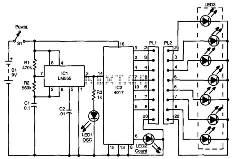
This circuit can be used to check up to an eight-conductor cable. IC1, a 555 timer, drives decade counter IC2, a 4017. Each LED should light in sequence. The cable to be tested is connected between PL1 and PL2....