
5V Power Supply For On-Train Radio Camera
In the schematic depicted in Figure 1, the DC voltage enters the supply circuit and is buffered by capacitor C1, which mitigates brief power interruptions. The reserve power source comprises four GoldCaps connected in series, each rated at 22 F / 2.3 V, yielding a total capacitance of 5.5 F / 9.2 V. It is crucial that the maximum charging voltage does not exceed 9.2 V, which is managed by a modern adjustable low-drop voltage regulator (LT1086) set to an output voltage of 9.57 V, taking into account a 0.6 V drop across diode D5. The LT1086 can handle a current of 1.5 A with current limiting, allowing for rapid charging of completely depleted GoldCaps.
When DC voltage is available, the GoldCaps are charged through diode D2. During this time, the camera operates directly from the track voltage via diode D4. Diode D5 prevents the track voltage from reaching the capacitor bank, while D4 ensures that the GoldCaps do not discharge back through the track when no voltage is present. Together, D4 and D5 function as an OR gate. The radio camera requires a 5 V supply and consumes approximately 70 mA, necessitating an output stage that includes a standard 7805 fixed voltage regulator alongside the typical capacitors (C9, C10, C11). Two low-current LEDs indicate the presence of voltage on the track and the charge status of the storage capacitors, although these can be omitted if not required. It is recommended that the 100 nF capacitors be placed as close as possible to the voltage regulators to ensure optimal performance.
This circuit design effectively balances the need for immediate power availability with environmental considerations, using GoldCaps as a rapid charging and discharging solution. The inclusion of diodes and voltage regulators ensures that the camera remains operational under varying conditions, providing a reliable solution for model railway enthusiasts.A radio camera on a model railway should transmit constantly while the train is moving and continue transmitting for a few minutes after the train stops. But if the train starts up again after a relatively long halt, imagery should be transmitted immediately.
Consequently, the power source for the camera cannot be rechargeable batteries (since the y take too long to charge), nor can it be primary batteries (for environmental reasons). Instead, GoldCaps provide a good alternative. They can be charged in no time flat, and they assure sufficient reserve power for operating the radio camera for a few minutes. Coming from the left in the schematic shown in Figure 1, the dc voltage arrives at the supply circuit and is buffered by capacitor C1, which bridges brief power interruptions.
The actual reserve power source consists of four GoldCaps connected in series, each rated at 22 F / 2. 3 V, which yields a net capacitance of 5. 5 F / 9. 2 V. The maximum charging voltage must never exceed 9. 2 V. This is ensured by a modern adjustable low-drop voltage regulator (LT1086), which is set to a nominal output voltage of 9.
57 V by resistors R2 and R3 (since there is an 0. 6-V voltage drop across D5). The LT1086 can handle a current of 1. 5 A (with current limiting), so even completely empty GoldCaps can be charged in a few seconds. Whenever the dc voltage is present, the GoldCaps are charged via D2. When the dc voltage is present, the camera is not powered from the Gold-Caps, but instead directly from the track via D4. Diode D5 prevents this voltage from reaching the bank of capacitors, and D4 prevents the GoldCaps from discharging via the track when no voltages present on it.
D4 and D5 thus form a sort of OR gate. The radio camera used by the author requires 5 V and draws a current of approximately 70 mA. This means the circuit must have an output stage consisting of a normal` 7805 fixed voltage regulator and the usual capacitors (C9 C10, C11). The two low-current LEDs respectively indicate whether voltage is present on the track and whether the storage capacitors are charged.
They can also be omitted. The 100-nF capacitors must be placed as close as possible to the voltage regulators. 🔗 External reference
Related Circuits
To build a Spectrum analyzer I needed a tuner. I also needed to learn how to control the tuner. In some old broken TV I found the tuner UV916. It is a common used tuner. The tuner is PLL...
This is a compact collection of amplifiers configured in a bridge connection. The output power is low, making them suitable for general applications. They can be utilized with small active loudspeakers, car stereos, and similar devices. The only limitation...
This battery-powered metal detector utilizes four exclusive-OR gates from the 4030 CMOS integrated circuit. The gates are configured as twin oscillators, with a search coil acting as the inductance element in one of the oscillators. When the coil approaches...
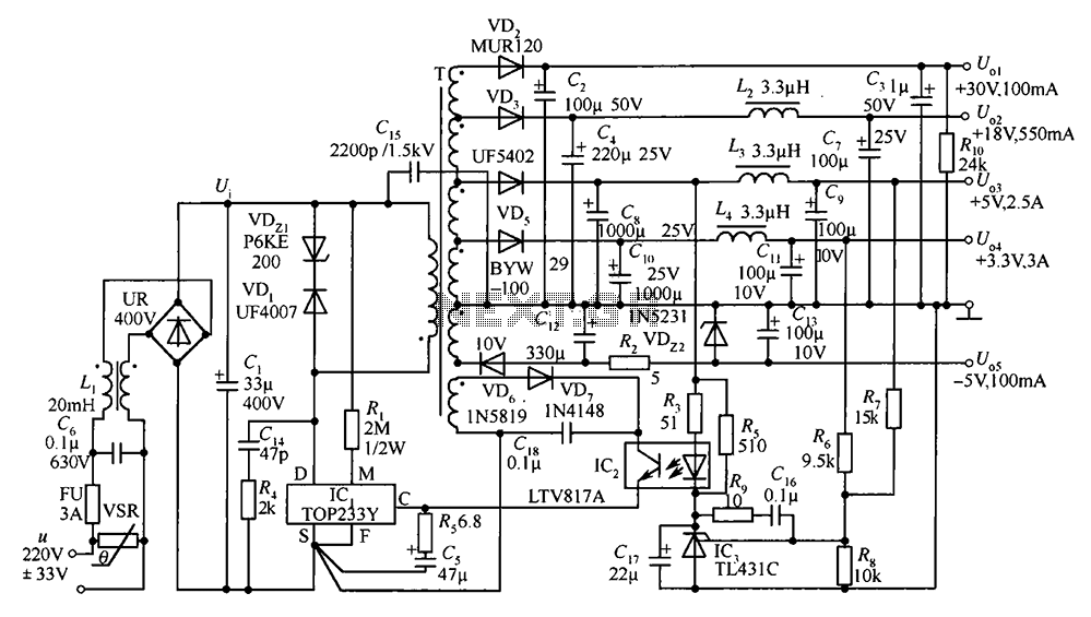
A 35W switching power supply circuit designed for a set-top box output is depicted in Figure 5. It features five distinct voltage outputs: Uo1 (+30V, 100mA), Uo2 (+18V, 550mA), Uo3 (+5V, 2.5A), Uo4 (+3.3V, 3A), and Uo5 (-5V, 100mA)....
A power supply project that operates without a traditional transformer, potentially saving costs but also presenting lethal voltages at the output terminals. This project should not be attempted by beginners due to the electric shock hazard. In the UK,...
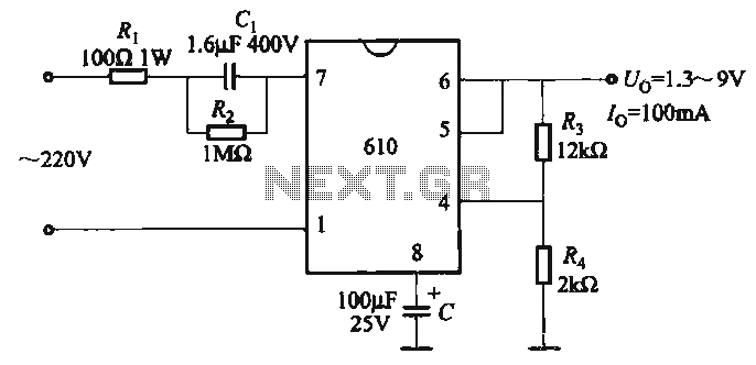
The output voltage can be calculated as follows: U = 1.3 (1 + R3 / R4) (V), where R3 and R4 are part of an adjustment potentiometer, allowing for a continuously adjustable output voltage. The described circuit involves a voltage...