
6-Channel Running Light
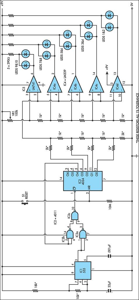
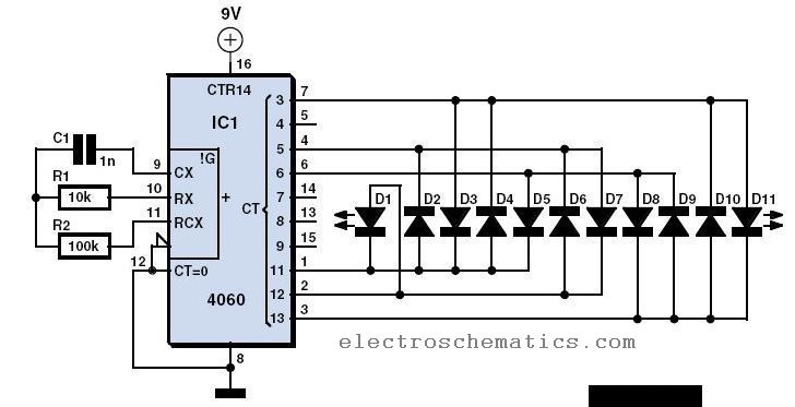
The running light circuit is designed to create a sequential lighting effect using seven LEDs. The primary components include two integrated circuits which serve different functions: one IC acts as a timer while the other operates as a decade scaler. The timer IC is responsible for generating timing pulses that control the sequence of the LEDs, ensuring that they light up in a specific order.
A resistor is included in the circuit to limit the current flowing through the LEDs, preventing them from drawing excessive current that could lead to damage. The value of this resistor is selected based on the forward voltage and current specifications of the LEDs used.
The capacitor in the circuit works in conjunction with the timer IC to establish the timing intervals between the LED activations. By charging and discharging, the capacitor helps to determine how long each LED remains illuminated before the next one in the sequence turns on.
The decade scaler IC is crucial in this circuit as it divides the input frequency from the timer IC by ten, allowing for a controlled and manageable sequence of LED activations. This IC ensures that the LEDs light up in a staggered manner, creating a visually appealing running light effect.
Overall, this running light circuit is an effective demonstration of basic electronic principles, integrating timing, current control, and sequential logic to achieve a dynamic lighting display.The circuit of the running light comprises two integrated circuits (ICs), a resistor, a capacitor and seven light-emitting diodes (LEDs), Decade scaler IC.. 🔗 External reference
Related Circuits
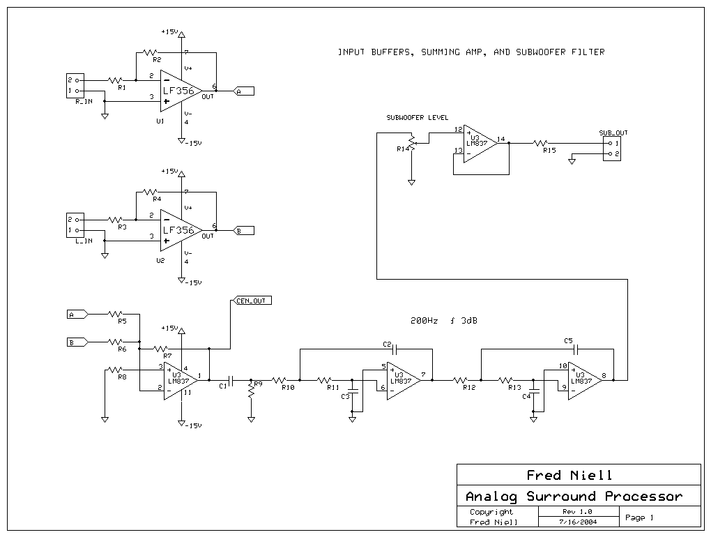
The overall block diagram of the system shows that audio input enters from the left and undergoes various processing steps including summation, differencing, multiplication, delay, and filtering. The output consists of five discrete audio channels along with one low-frequency...
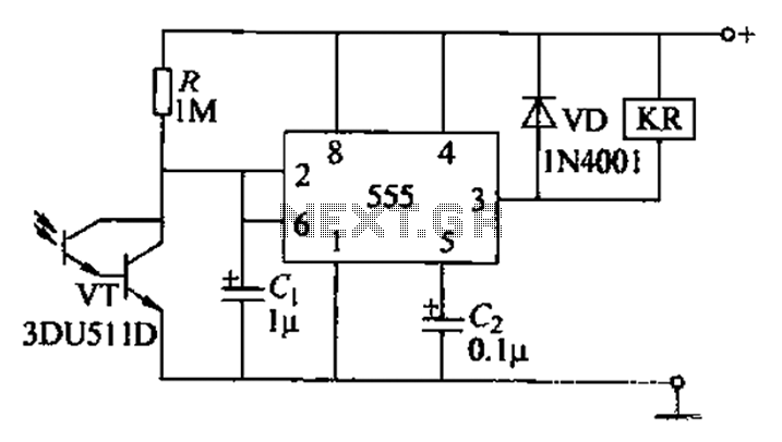
The circuit utilizes a Darlington-type phototransistor as the sensing element, which enhances sensitivity to low light levels, making it suitable for detecting reflected light signals. When the Darlington phototransistor is exposed to light, its resistance decreases, causing the voltage...
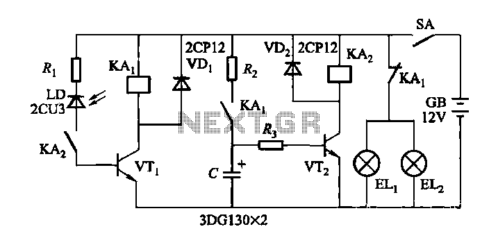
When driving at night and approaching another vehicle, traffic regulations dictate that the distance between the two vehicles should be maintained. This is achieved by alternately activating and deactivating the high beams, while utilizing either the wide lights or...
With RFT illuminated, point R goes to 0 volt and LM runs. With LFT illuminated, point R goes to 0 volt and RM runs. With RFT and/or LFT not illuminated, points R/L go to +9 volt; P1 and P2...
This circuit replicates the starting light sequence currently utilized by FISA for Formula One racing. It can be applied to slot car sets (such as HO scale AFX/Life Like/Tyco sets) or radio-controlled cars. IC1, a 555 timer integrated circuit,...
Have you already set up a Christmas tree in your house and decorated it with traditional lights? Build a couple of these LED lights to enhance the Christmas atmosphere. The project involves creating LED lights that can be used to...