
Analog 6-channel Home Theatre Audio Project
The design process for the audio system emphasizes the importance of each component in achieving high-quality sound reproduction. The front end's use of gain 1 buffer amplifiers ensures that signal integrity is maintained while minimizing distortion. The summation and differencing of the left and right audio signals allow for the creation of a center channel output, enhancing the surround sound experience. The implementation of a 9-pole low-pass filter for the subwoofer ensures that only low-frequency signals are passed through, providing a powerful bass response without interference from higher frequencies. Similarly, the two-pole high-pass filter for the center channel effectively eliminates low-frequency noise, allowing for clearer dialogue and sound effects.
The delay system is crucial for creating a realistic spatial audio experience. By employing analog techniques, the project seeks to replicate the time-based effects typically managed by digital processors in commercial systems. The concept of "gain riding" allows for dynamic adjustment of audio levels, providing a more immersive listening experience. The overall architecture of the system reflects a thoughtful approach to analog sound design, demonstrating that high-quality audio reproduction can be achieved through innovative engineering and resourcefulness. The use of repurposed components not only highlights sustainability but also showcases the potential for creativity in electronics design, particularly in the realm of audio technology. Each section of the schematic is meticulously crafted to ensure optimal performance, with careful consideration given to the interaction between components and the overall system functionality.The overall block diagram of the system. Audio comes in at the left, and is summed, differenced, multiplied, delayed, filtered, and all other imaginable manipulations. The output is a set of 5 discrete audio channels plus one low frequency effects channel. This is the typical layout for the speakers in a 5 + 1 channel home theatre system setup. The chair sits in the middle and the speakers are amied more or less at the listener. The subwoofer`s location is less important, as it is nearly omnidirectional. In this age of Dolby Digital and dts decoding standard on recievers under about $200, you might wonder why I decided to do this project at all. Two reasons: 1) at the time I was a graduate student in physics, and therefore had no money to buy a $200 reciever, and 2) I am a strong believer in analog electronics when it comes to audio.
Since I can`t afford to purchase the single-chip surround solutions available from a few manufacturers, (and for that matter can`t afford to buy new components) I decided to build the entire system from my junk box, with the exception of a few potentiometers from Radio Shack. While my CD player is indeed better at accurately reproducing sound than many LP`s, I just can`t give up the panache of analog sound reproduction.
So, I set about to create a Dolby Pro Logic surround sound style system without the aid of digital wizzardry using junk parts. I started at the Dolby Labs web site, downloading their "white paper" documents on their Pro Logic system.
While there are no schematics available, there is extensive documentation on the theory of their system [Figure 1]. The Pro Logic system takes the two channel output from a stereo source, and decodes it into 5 or 6 discreet channels of sound, depending on the sophistication of the system.
Typically, the signals from the stereo source are digitized, and the math and delays are done with a dedicated processor. The digital signals are then converted back to analog, and sent to the amplifiers. Clearly, getting all the functions done using analog trechniques was not going to be easy. In particular, the delay was going to prove difficult. Their "steering" matrix system (at the time I was researching it) was not well-described, so I had to improvise my own solution.
More recently, it has become clear that I chose a system called "gain riding, " as noted on the Dolby home page. The schematic is shown in figures (2, 3, . ). I found that designing the system in parts was helpful, so the schematic is presented as such. The system is broken down into the front end, the delay and noise circuit, the steering matrix and amplifers, and the power amplifiers.
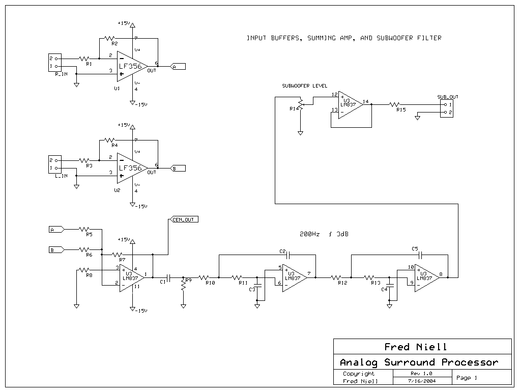
The front end is the heart of the surround system. The input utilizes the Haefler matrix idea, but extends it a bit farther. To begin, we have a gain 1 buffer amplifer for each channel. The signals are then level-shifted and sent to input buffers. The Right (Pre-InR) and Left (Pre-InL) signals are summed and differenced with standard op-amp circuits. The resulting InR - InL signal is subtracted off of the Pre-InR and Pre-InL, giving the post line-outs.
The line-outs go to gain 1 buffers with 100 ohm output impedance. The summed Pre-InR and Pre-InL are fed to the center channel output buffer and filter, and the subwoofer filters. The subwoofer filter is a 9-pole low-pass filter set at 200 Hz, with an overall gain of 1. The center channel filter is a two-pole high pass set at 800 Hz. The front end was designed taking into account the smallest details to reduce noise and hum. Devising a delay system proved to be difficult. I spent a lot of time going down blind alleys with barrier bucket designs and actual long-delay cable.
However, I remembered having seen a Fisher tube amp from the 60`s that utilized a "spatializer. " The spatializer consisted of a driver and reciever circuit for a spring reverb unit. Since I had recently torn down a Peavy amp 🔗 External reference
Related Circuits
The circuit provides three channels of optically isolated input suitable for various precision signal-acquisition applications. It operates using a single 15-V power rail with a ground common to the analog-to-digital converter. The multiplexer functions through a standard quad-channel optoisolator...

The LTC3113 fixed frequency buck-boost DC-DC converter can be utilized to design various power supply circuits that operate with input voltages that are above, below, or equal to the output voltage. The topology integrated into the IC ensures low...
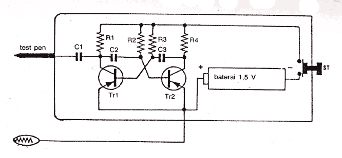
Audio Jammer Noise generator for detector audio circuit More: Parts: R1,R4 . 1K 0,5W R2,R3 . 39K 0,5W C1 . 5000pF/50V C2,C3 . 3000pF/50V FCS9012 . PNP FCS9012 . PNP The audio jammer circuit functions as a noise generator, designed...
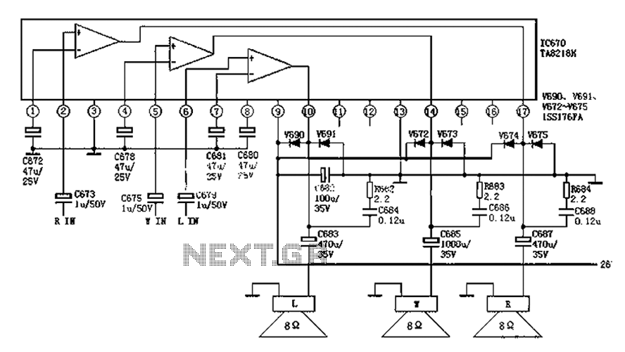
The audio circuit depicted in the figure is commonly utilized in color television systems. The pin functions and reference voltages for the TA8218AH are as follows: Pin 1: 1.9V - inverting input; Pin 2: 2.1V - R-channel audio signal...
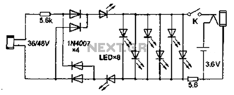
Also known as the Free lamp (commonly referred to as the Myanmar lamp by online sellers), this device operates using the voltage from a standard household fixed telephone line, eliminating the need for batteries or AC power. The lamp...
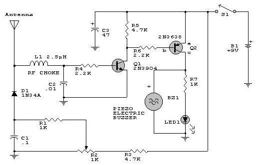
This electronic RF detector project is designed using common transistors and a few standard electronic components. The RF detector responds to RF signals below the standard broadcast band and well over 500 MHz, providing both visual and audible indications...