
led flasher circuit schematic inside

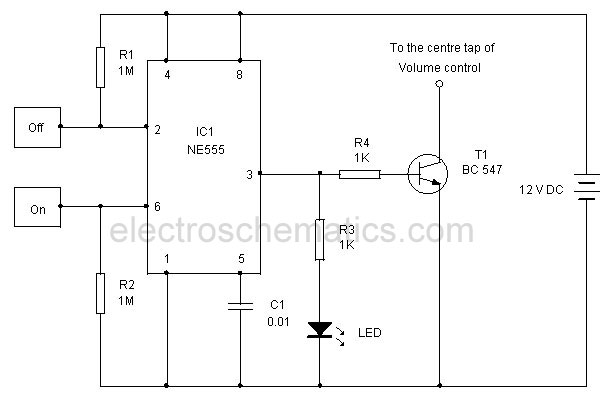
This circuit design aims to create a visually engaging LED flasher using five NE555 timer integrated circuits (ICs), which are widely recognized for their versatility in timing applications. Each NE555 timer will drive one pair of LEDs, allowing for independent control of the flashing rates. The use of trimmer potentiometers (trim pots) will enable fine-tuning of the flash rates for each LED pair, providing a customizable user experience.
The orientation of the LEDs is crucial for the desired operation of the circuit. The lower row of LEDs should be connected to the output of the NE555 timers in a way that allows them to illuminate when the output is high. Conversely, if the top row is meant to light up during a low output, the connections must be verified and corrected if necessary to ensure proper functionality.
In terms of component selection, the NE555 timer requires bypass capacitors for stable operation. According to the datasheet, each timer should have a 0.1 µF ceramic capacitor connected between the supply pin and ground to filter high-frequency noise. Additionally, a larger capacitor of at least 1 µF should be included for further stabilization. The entire circuit benefits from a 100 µF capacitor, which acts as a reservoir to smooth out fluctuations in the power supply, particularly when powered by a PC power supply. While PC power supplies generally provide stable voltage, incorporating this capacitor can enhance performance by further reducing any residual noise.
The layout of the trim pots should be strategically placed within the circuit to allow easy access for adjustments. The values for these pots can be determined through experimentation, typically starting with values in the range of 10 kΩ to 100 kΩ, depending on the desired range of flash rates. It is advisable to simulate the circuit in Eagle or similar software to visualize the effects of varying the trim pot values on the LED flashing rates.
In conclusion, this circuit design not only serves as a practical exercise in using NE555 timers but also provides a platform for learning about component selection, circuit layout, and the importance of proper schematic representation. Careful attention to the orientation of the LEDs and the inclusion of necessary bypass capacitors will ensure reliable operation and an engaging visual display.Build a circuit that will flash 5 pairs of LEDs at variable rates. To do this I designed a circuit using 5 NE555 timers. To control the variable flash rate I want to use trim pots. I am having a hard time figuring out where to lay out the trim pot and what value to use. Can some one please help me I have attached a screen cap of the schematic I designed in eagle. I`ve had a couple of beers, so maybe I`m not seeing this right, but it looks to me as if the top row of Leds are the wrong way round. It looks like the lower row will light when the output is high, but if the top row is meant to light on output low, they are the wrong way round. Thanks for the replies guys. As I said I am very new to this and designed the schematic in eagle after watching a few tutorials. I am basing my electronics knowledge off of 3 electronic classes I took back in high school. After 7 years the knowledge gained in those classes has faded somewhat. The season I had not completed the circuit is because I was waiting on figuring out what value trimpot to use.
The tutorial I spoke of was a tutorial on how to use Eagle, not on the flasher circuit. My current knowledge on circuit design comes from some classes taken back in high school and most recently reading a few of Forrest Mims books. Your schematic is a negative. I fixed it. You saved it as a fuzzy JPG file type instead of as a very clear GIF or PNG file type so that is why it looks fuzzy.
The datasheet for the LM555 shows two supply bypass capacitors. A 0. 1uf ceramic disc and at least 1uF. Each 555 should have a 0. 1uF ceramic disc and the entire circuit should have 100uF. I have the background set to black in Eagle. I am a professional photographer and almost all of my photo editing work is done on a black background as it is much easier on the eyes. When I found out I could change the workspace in eagle to black I did. I just was to lazy to change it back to white before taking the screen cap. I saved it as a quality 90 jpg and on 4 of my computers it looks fine, but for every ones convenience I will save them as.
gif from now on. This circuit will be powered by a pc power supply so is the 100uF necessary to filter out noise or does the pc power supply do a good job of filtering anyway 🔗 External reference
Related Circuits
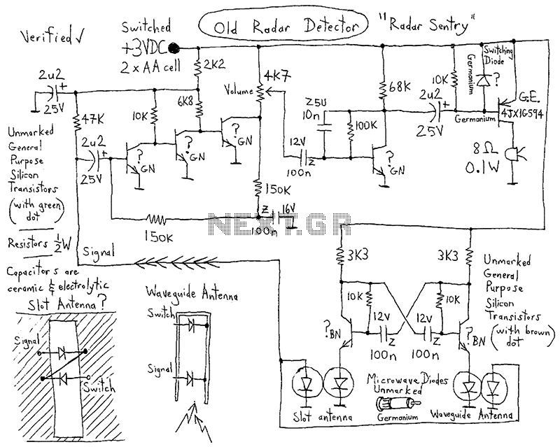
A CI-22BG tube and a CI-3BG tube were purchased for a total of 16G. Due to the lack of radioactive materials for testing the Geiger counter, a piece of radioactive Fiesta dinnerware was ordered from eBay. Red Fiestaware historically...
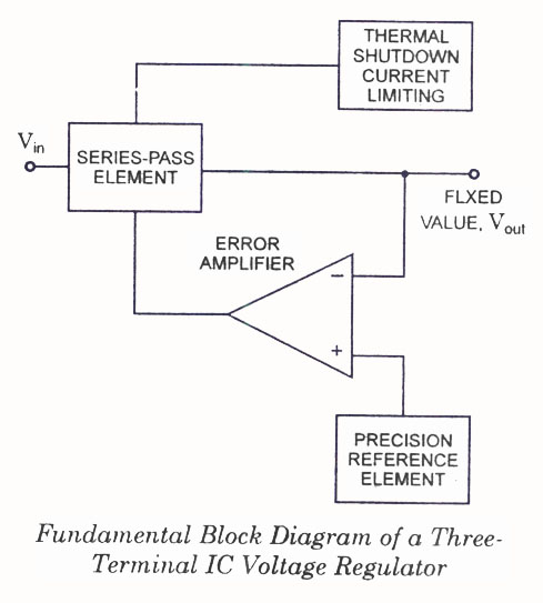
IC Voltage Regulators - Circuit diagram and block diagram of linear, fixed, adjustable (positive and negative), and switching voltage regulators. IC voltage regulators are essential components in electronic circuits, providing stable output voltages from a varying input voltage source. They...
The tank circuit consisting of capacitor C2 and inductor L1 is utilized to tune the transmitter. The antenna is coupled to the transmitter through capacitor C3 and can be either a telescopic antenna or a length of hookup wire....

The circuit expands a single 15-pin D-sub VGA output to multiple outputs, allowing for the connection of up to six monitors simultaneously. The input VGA connector is positioned on the left side, while the six output VGA connectors are...
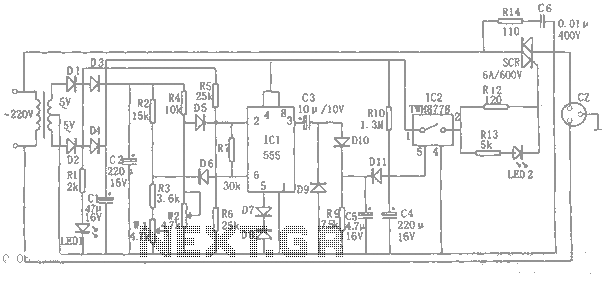
An automatic power protection circuit is presented. This protection includes a step-down rectifier circuit, an overvoltage and undervoltage detection circuit, and a delay switch control circuit. The step-down circuit is responsible for the entire rectifier circuit's DC voltage. The automatic...
This touch-controlled musical bell circuit generates a musical tone whenever someone touches the designated touch point (TP). The circuit operates using two AA batteries and produces sufficient sound output. It utilizes the UM3481 integrated circuit, which is commonly employed...