
60W Bass Amplifier and Preamp

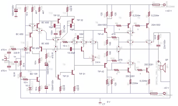
This power amplifier circuit is designed to operate with a single-rail voltage supply of approximately 60V, which is typical for high-power audio applications such as guitar amplifiers. The circuit employs capacitor coupling to connect to the loudspeakers, which helps in blocking any DC voltage present in the amplifier output, thereby protecting the speakers from potential damage caused by DC signals.
The inclusion of capacitor C8 serves a dual purpose. Primarily, it acts as a coupling capacitor, but it also provides a degree of protection for the loudspeakers. In the event of a failure in the output transistors, C8 prevents the high voltage from the power supply from reaching the speakers, which can safeguard them against damage. The suggested minimum capacitance value for C8 is mentioned, but it is advisable to use a capacitor with a higher capacitance, such as a 3300µF or a combination of two 2200µF capacitors in parallel, to enhance performance and reliability.
The preamplifier stage of this circuit is powered by the same 60V supply as the power amplifier, which simplifies the overall design and reduces the need for additional power supply circuits. The preamp utilizes a two-transistor gain block configuration, capable of delivering approximately 20V RMS output. This configuration is beneficial as it provides high input overload capability, allowing the amplifier to handle transient signals without distortion or clipping.
Regarding the choice of transistors, it is noted that the Darlington transistor types initially specified may be oversized for this application. While Darlington pairs are known for their high current gain, selecting appropriately rated transistors that are not excessively powerful can improve efficiency and reduce unnecessary heat generation within the circuit. Substituting with smaller, suitable transistors could optimize the amplifier's performance while maintaining reliability.
Overall, this circuit design exemplifies a robust approach to building a high-power guitar amplifier with essential protective features and efficient gain stages.This design adopts a well established circuit topology for the power amplifier, using a single-rail supply of about 60V and capacitor-coupling for the speaker(s). The advantages for a guitar amplifier are the very simple circuitry, even for comparatively high power outputs, and a certain built-in degree of loudspeaker protection, due to capacitor C8, preventing the voltage supply to be conveyed into loudspeakers in case of output transistors' failure.
The preamp is powered by the same 60V rails as the power amplifier, allowing to implement a two-transistors gain-block capable of delivering about 20V RMS output. This provides a very high input overload capability. The value listed for C8 is the minimum suggested value. A 3300µF capacitor or two 2200µF capacitors wired in parallel would be a better choice. The Darlington transistor types listed could be too oversized for such a design. You can substitute them 🔗 External reference
Related Circuits
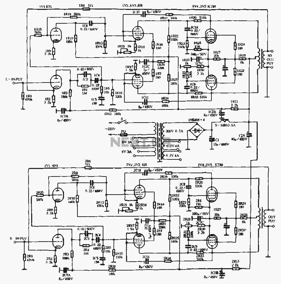
A standard linear amplifier is designed according to a conventional circuit configuration, with the power of the beam tube indicated in Figure 1-8. The output stage employs power tubes such as EL34, KT88, and KT100, which are types of...
The CL type circuit is not a power amplifier output capacitance, feedback capacitance, or compensation capacitor amplifier circuit; it operates solely through a transistor (or FET) and a resistor. This circuit can generate feedback, and phase shift elements are...
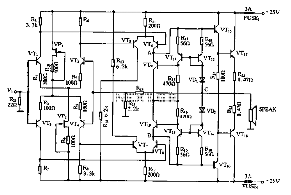
This post presents the circuit schematic diagram for a 500-watt mono power amplifier. As of July 18, 2012, the intention is to create a power sound system with a total output of 1000 watts in stereo. The design utilizes...

The AC negative feedback circuit consists of resistors R and R, as illustrated in Figure 1-30. In this configuration, capacitor C3 can be treated as a short circuit. The actual results are depicted in Figure 1-32. An AC voltage...
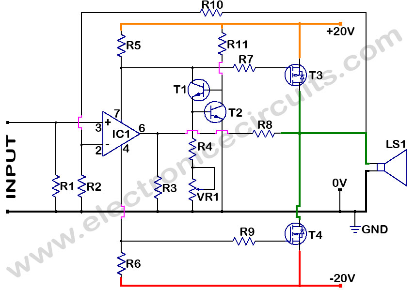
MOSFET Power Amplifier Circuit diagrams. Two complementary MOSFETs are used to deliver 20W into 8Ω. The described MOSFET power amplifier circuit utilizes two complementary MOSFETs, which are arranged in a push-pull configuration to efficiently amplify audio signals. The circuit is...
To complement the 60 Watt MOSFET audio amplifier, a high-quality preamplifier design was necessary. A discrete components topology using +24V and -24V supply rails was chosen, minimizing the transistor count while still achieving low noise, very low distortion, and...