
60W x2 standard linear type tube amplifiers
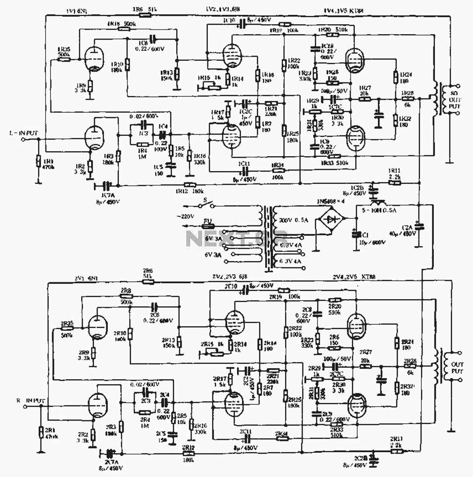
The described linear amplifier is a versatile audio amplification device that employs a push-pull configuration to enhance output power and reduce distortion. The circuit is designed to operate in Class AB mode, which allows for efficient operation while maintaining sound fidelity. The semi-fixed bias method provides a balance between fixed and cathode bias, ensuring stable operation across varying conditions.
The EL34, KT88, and KT100 tubes are selected for their robust performance characteristics, with each offering different output power capabilities. The EL34 tubes, known for their warm sound and musicality, are suitable for applications requiring 40W output per channel. The KT88 tubes, recognized for their high power handling and dynamic range, can provide 60W output per channel, making them ideal for more demanding audio environments. The KT100, with its even greater power handling capability, allows for a maximum output of 80W per channel, suitable for larger systems or venues.
In terms of circuit design, the amplifier typically includes input and output transformers to match impedance and facilitate signal transfer. Additionally, feedback mechanisms may be incorporated to further refine the audio quality and minimize distortion, ensuring that the output faithfully reproduces the input signal.
Overall, this linear amplifier design exemplifies a balance of power and performance, making it an excellent choice for audio enthusiasts and professional sound applications alike.Standard linear amplifier according to the standard connection conventional circuit configuration, the power of the beam tube tube according to Figure 1-8, the river. The output stage uses power tubes EL34, KT88. KT100 and other radio beam tetrode, belongs to a class AB push-pull amplifier circuit as early as the gate bias circuit is neither completely fixed bias, is not entirely cathode bias, instead of using semi-fixed bias pressure way. When the output tube using EI.34 as push-pull amplification, each output power up. 40W 2; using KT88 push-pull as you zoom in, each output power up to 60W 2; when using the KT100 as a push-pull amplification, each output power up to 80wX 2.
Related Circuits
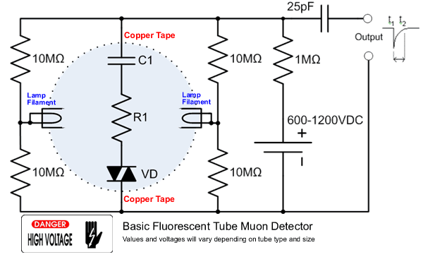
This project focuses on the development of a low-cost cosmic ray detector utilizing common fluorescent tubes. It is based on an experiment conducted in 2000 by Dr. Schmeling at CERN, which demonstrated a straightforward method for detecting and visualizing...
This project was a surprise as the BC547 transistor (equivalent to 2N2222) can be used to construct a 500mW linear amplifier that operates across the entire HF band with excellent spectral purity and without the need for neutralization. The...
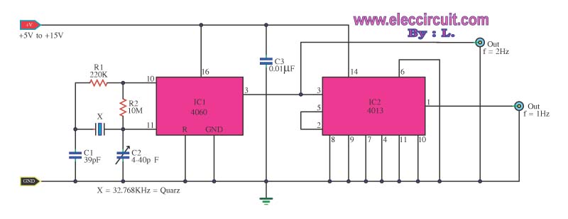
This is a standard digital clock circuit with a frequency of either 1 Hz or 2 Hz. It can be utilized in a conventional clock circuit. The circuit comprises IC-4060 and IC-4013. The digital clock circuit operates by utilizing the...
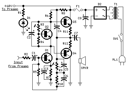
This design utilizes a well-established circuit topology for the power amplifier, employing a single-rail supply of approximately 60V and capacitor coupling for the speakers. The advantages of this configuration for a guitar amplifier include a straightforward circuit design, even...
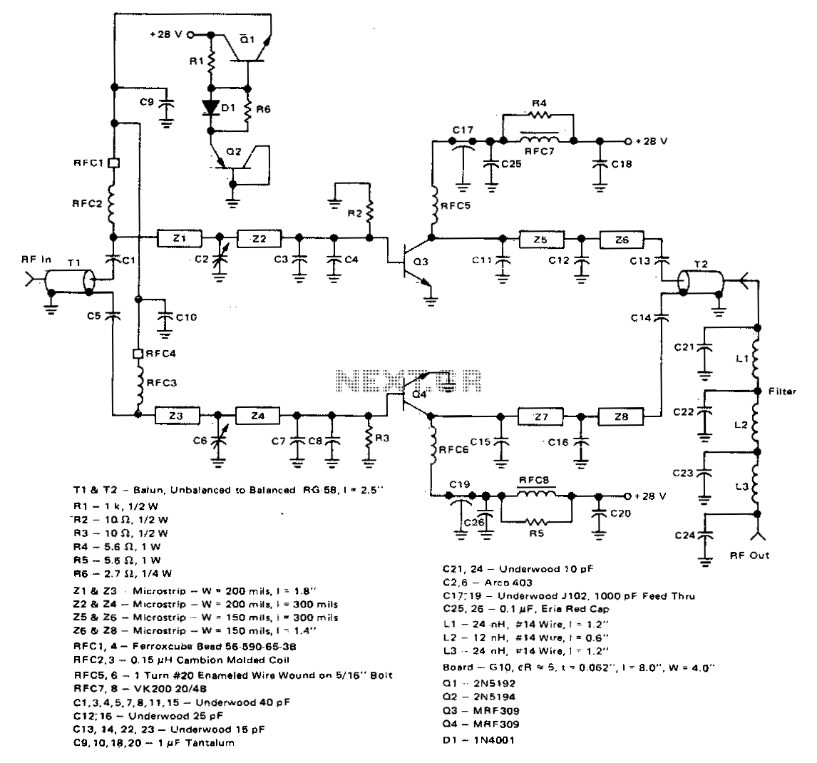
This 100-watt linear amplifier can be built using two MRF309 transistors in a push-pull configuration, requiring only 16 watts of drive power within the frequency range of 420 to 450 MHz. It operates from a 28-volt supply and achieves...
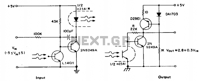
The accuracy of direct linear coupling of analog current signals through an optocoupler is influenced by the linearity of the coupler and its temperature coefficient. Implementing an additional coupler for feedback can enhance linearity, but only if both couplers...
Warning: include(partials/cookie-banner.php): Failed to open stream: Permission denied in /var/www/html/nextgr/view-circuit.php on line 713
Warning: include(): Failed opening 'partials/cookie-banner.php' for inclusion (include_path='.:/usr/share/php') in /var/www/html/nextgr/view-circuit.php on line 713