
XR2211 Linear FM Detector

The linear FM detector circuit is designed to demodulate frequency-modulated signals by converting variations in frequency back into their original amplitude-modulated form. This functionality is essential in various applications, particularly in telemetry, where data is transmitted over distances and must be accurately received and interpreted.
The circuit typically consists of several key components, including a mixer, a phase-locked loop (PLL), and a low-pass filter. The mixer combines the incoming FM signal with a local oscillator signal to produce an intermediate frequency (IF) signal. This IF signal is then processed by the PLL, which locks onto the frequency of the incoming signal, ensuring that the demodulation process remains stable and accurate. The output of the PLL is then passed through a low-pass filter to remove any high-frequency components, resulting in a clean demodulated signal that represents the original information.
In telemetry applications, this linear FM detector circuit can be employed in various sensor systems, where data collected from remote locations is transmitted wirelessly. The ability to accurately demodulate these signals is crucial for ensuring data integrity and reliability. Additionally, the circuit may be optimized for specific frequency ranges or bandwidths, depending on the particular requirements of the communication system in which it is implemented.
Overall, the linear FM detector circuit plays a vital role in the field of analog communications, facilitating the effective transmission and reception of information across diverse applications.This is a linear FM detector circuit. This circuit usually is used in telemetry applications and wide range of analog communications. The main part of this.. 🔗 External reference
Related Circuits
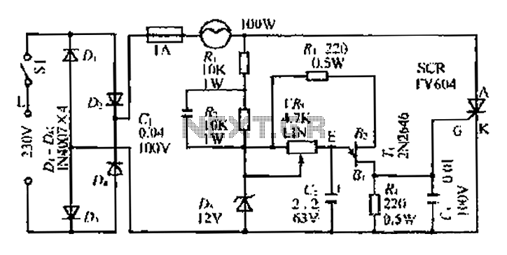
An AC voltage of 30V is rectified. The positive terminal is connected to a fuse and a 100W bulb, while the negative terminal is connected to a thyristor. A Zener diode provides a stable bias voltage. A variable resistor...

A simple metal detector circuit diagram and schematic using a single transistor and a radio. This metal detector/sensor project is easy to make and is an application of a Colpitts oscillator. The metal detector circuit utilizes a single transistor in...
This metal detector schematic circuit is based on a transistor radio as a detector. This metal detector is entirely different from other metal detectors because this circuit does not have a speaker. With the radio tuned to a weak...
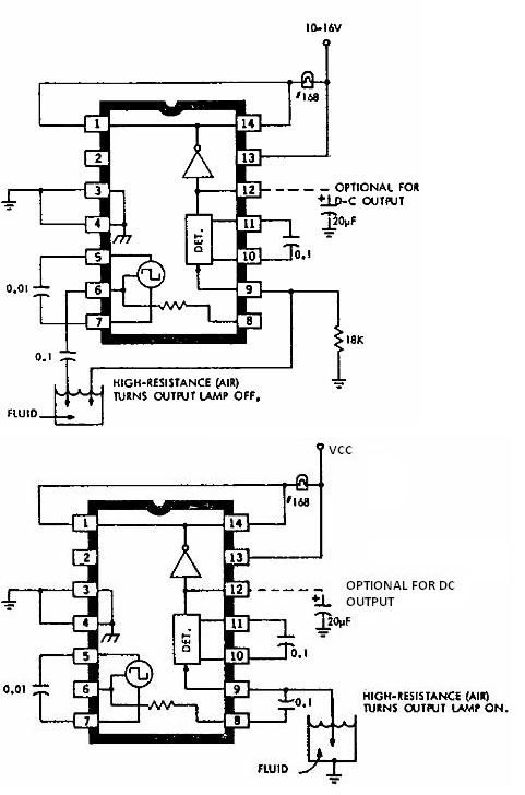
This electronic liquid detector circuit diagram is based on the ULN2429 monolithic bipolar integrated circuit designed for detecting the absence or presence of many different types of liquids. The ULN2429 electronic liquid detector circuit can be used in automotive,...

Portable loads such as video cameras, halogen flood lights, electrical irons, hand drills, grinders, and cutters are powered by connecting long 2- or 3-core cables to the mains plug. Due to prolonged usage, the power cord wires are subjected...

This circuit is designed to detect electrical wires connected to the mains (live wire). It features an LED for visual indication and a buzzer for audio alerts. As the detector is brought closer to the electrical wire, the LED...