
Triac motor drive circuit
The triac motor drive circuit is designed to control the operation of AC motors using a TRIAC as the primary switching element. A TRIAC is a semiconductor device that can conduct current in both directions when triggered, making it suitable for controlling AC loads. The circuit typically includes components such as resistors, capacitors, and diodes, which work together to manage the triggering and operation of the TRIAC.
In the configuration shown in figure (a), the main components are arranged to ensure that the TRIAC can be triggered at the appropriate phase angle of the AC waveform. This phase control allows for variable speed operation of the motor, as adjusting the triggering point alters the effective voltage and current supplied to the motor.
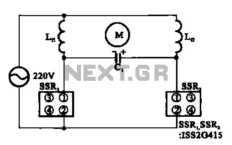
Figure (b) illustrates how the motor coils are connected to the circuit. The connections must be made carefully to ensure that the motor operates efficiently and safely. The design may also incorporate protective elements such as fuses or circuit breakers to prevent damage from overcurrent conditions.
The overall design of the triac motor drive circuit emphasizes reliability and efficiency in motor control applications, making it ideal for various industrial and consumer applications. Proper thermal management is also essential, as TRIACs can generate heat during operation, necessitating the use of heat sinks or other cooling methods to maintain optimal performance.Triac motor drive circuit b Shows the motor drive circuit TRIAC TRIAC has been called solid state relays. Figure (a) shows a circuit configuration diagram (b) shows the connection of the motor coils.
Related Circuits
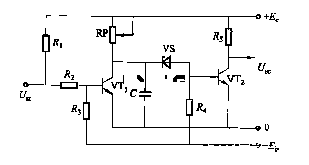
The circuit is a rechargeable short delay control for a conducting pipe, featuring two adjustment potentiometers (RP) that enable the delay time to be set from several hundred milliseconds to several seconds. The rechargeable short delay circuit is designed for...
This circuit illustrates a color sensor circuit diagram. The design is grounded in the principles of optics and digital electronics. The color sensor circuit typically employs a light-sensitive component, such as a photodiode or phototransistor, to detect and differentiate colors...
The 555 IC is configured in an astable mode, producing a frequency that remains constant and is independent of the duty cycle. The total resistance (Rcharge + Rdischarge, considering the diode) is fixed at 22 kΩ, yielding a frequency...

This circuit diagram of a UPS is designed for use with cordless telephones that cannot operate during a power failure. Since the UPS is intended solely for telephones, its output power is limited to 1.5W. This UPS circuit is...
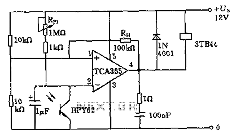
A bridge input circuit utilizing a phototransistor BPY62 and a power operational amplifier is capable of controlling power loads up to 8.5 kW. It features a voltage divider composed of two 10 kΩ resistors, creating a midpoint connection. The...
The electric car remote control circuit diagram enables the model car to move forward and backward, as well as turn left and right. It is simple and easy to operate. The radio remote control receiver demodulation circuit utilizes TWH9238...
Warning: include(partials/cookie-banner.php): Failed to open stream: Permission denied in /var/www/html/nextgr/view-circuit.php on line 713
Warning: include(): Failed opening 'partials/cookie-banner.php' for inclusion (include_path='.:/usr/share/php') in /var/www/html/nextgr/view-circuit.php on line 713