
Tone Control
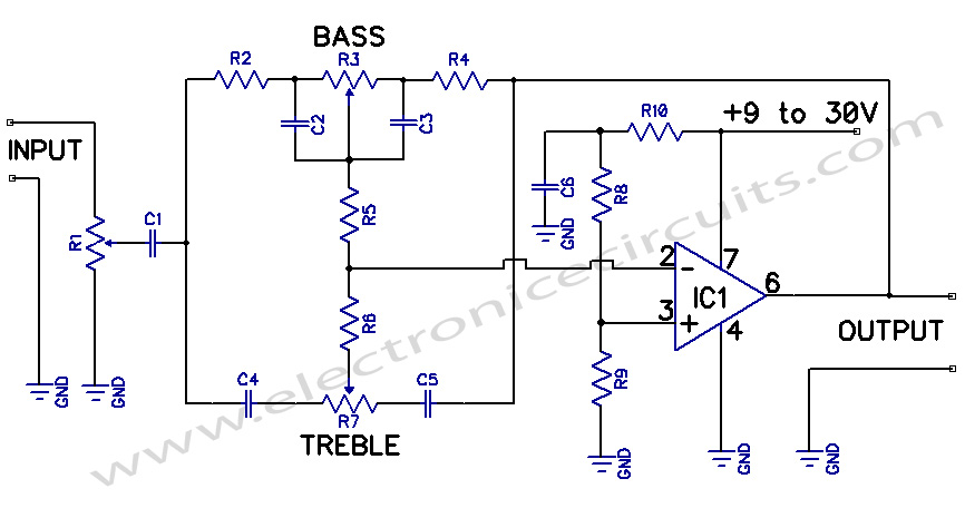
This circuit design utilizes operational amplifiers (op-amps) to achieve independent control over the bass and treble frequencies, allowing for enhanced audio customization. The preamplifier stage amplifies the audio signal before it is processed by the tone control section.
The bass control typically employs a low-pass filter configuration, which allows lower frequencies to pass through while attenuating higher frequencies. This is achieved by using capacitors and resistors in a feedback loop with the op-amp, where the cutoff frequency can be adjusted to the desired level.
Conversely, the treble control is implemented using a high-pass filter arrangement, permitting higher frequencies to pass while reducing the amplitude of lower frequencies. Similar to the bass control, this section also utilizes capacitors and resistors, with the op-amp configured to allow for fine-tuning of the treble response.
The output from both tone control sections can be mixed and fed into the output stage of the preamplifier, which may include additional amplification or buffering to drive the next stage in the audio signal chain. Power supply decoupling capacitors are also recommended to ensure stable operation and to minimize noise in the audio signal.
Overall, this preamplifier circuit with independent Bass and Treble controls is ideal for applications requiring customizable audio output, such as in home audio systems, musical instruments, or professional audio equipment. Proper layout and component selection are crucial for achieving optimal performance and minimizing distortion in the final output.Bass Treble Tone Control Circuit A preamplifier circuit providing independent Bass and Treble tone controls is shown in this circuit. The.. 🔗 External reference
Related Circuits
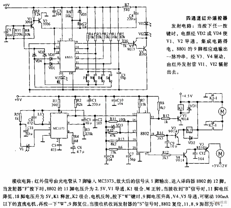
The receiving circuit involves an infrared signal being input to the MC3373 from pin 7 via a phototube. The amplified signal is output from pin 1 and sent to pin 12 of the decoder 8802. When the transmitter F...
Two stepper motors are to be controlled by a dsPIC microcontroller. The programming of the microcontroller has been completed, but there is confusion regarding the use of the L298 driver. Assistance is needed with the circuit design. To control two...
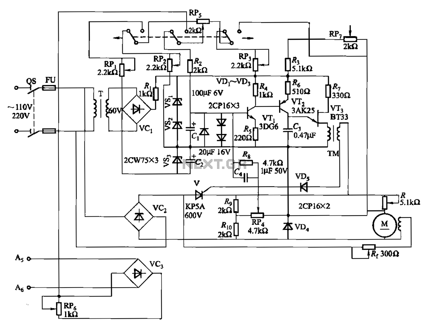
A 100W full-wave single-junction transistor trigger control circuit designed for constant or variable speed control of a wire feed motor. The input control signal consists of a voltage adjusted by the master potentiometer (RPs) and a feedback voltage from...
The Arduino Uno features an ATMEGA328P-PU microcontroller and various additional components on the board. The objective is to program the microcontroller without relying on the Arduino software, utilizing only the essential components. The goal is to develop projects independently...
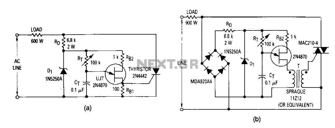
The most elementary application is a half-wave control circuit. The thyristor is acting both as a power control device and as a rectifier, providing variable power to the load during the positive half cycle and no power to the...
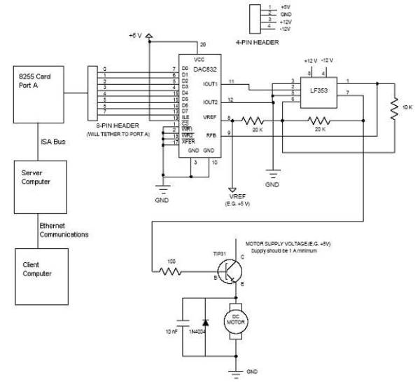
Open loop speed control of a DC motor is implemented using the 8255 Digital I/O Controller chip in conjunction with a TCP/IP server-client application programmed in Visual Basic. The DAC0832 chip serves as the Digital to Analog Converter. This...