
7 Segment LED Counter

The described counter circuit is designed to count incoming pulses, making it suitable for various applications such as customer counting systems in retail environments. The circuit operates using Transistor-Transistor Logic (TTL), which ensures compatibility with a wide range of digital logic signals.
The core of the circuit typically includes a binary counter IC, such as the 74HC393, which is a dual 4-bit binary counter. This IC can count up to 16 pulses before it resets, making it ideal for tracking the number of customers entering or exiting a store. The inputs of the counter can be connected to a sensor, like a phototransistor or a mechanical switch, that generates a TTL-compatible pulse every time a customer passes through the entrance.
To ensure accurate counting, the circuit may incorporate debouncing mechanisms if mechanical switches are used, preventing false counts due to switch bounce. Additionally, the output of the counter can be connected to a display module, such as a 7-segment display, to visually represent the count. This requires a decoder IC, like the 74HC4511, to convert binary output from the counter into a format suitable for the display.
For expansion purposes, additional counters can be cascaded by connecting the carry-out pin of one counter to the clock input of another, allowing for counting beyond the initial limit of a single IC. This modular approach facilitates scalability, enabling the design to accommodate higher pulse counts as needed.
Power supply requirements for the circuit typically involve a 5V DC source, which is standard for TTL logic circuits. Proper bypass capacitors should be included near the power pins of the ICs to mitigate noise and ensure stable operation.
In summary, this counter circuit is a versatile and expandable solution for counting applications, leveraging TTL logic to provide reliable performance in various environments.This simple counter can be used to count pulses, as the basis for a customer counter (like you see at the doors of some stores), or for anything else that may be counted. The circuit accepts any TTL compatible logic signal, and can be expanded easily (see Notes). 🔗 External reference
Related Circuits
The LED flasher circuits below operate on a single 1.5 volt battery. The circuit on the upper right uses the popular LM3909 LED flasher IC and requires only a timing capacitor and LED. The top left circuit, designed by...

Each bistable circuit comprises two oppositely-symmetrical germanium transistors, two diodes, and four resistors. An additional transistor, Q, facilitates the transition of the conducting state to the next position when actuated by a transfer pulse. The absence of capacitors allows...

This transistor has only one IC tester and can test all types of transistors. With two LEDs indicating the type of the transistor is NPN or PNP. The circuit uses a CMOS 4049 IC. The test transistor to terminals...
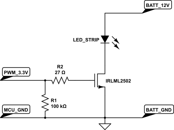
A strip of LEDs is controlled by a microcontroller using pulse-width modulation (PWM) to adjust brightness. The LED strip requires approximately 1.5A at 12V. The user, who has experience only with low-power digital electronics, seeks confirmation of their assumptions...
The bi-directional sequencer employs a 4-bit binary up/down counter (CD4516) along with two "1 of 8 line decoders" (74HC138 or 74HCT138) to create the well-known "Night Rider" display. A Schmitt Trigger oscillator generates the clock signal for the counter,...
A 10-light LED bar graph is desired, where the LEDs light up sequentially until all are lit, then cycle back down until all are off. The LM3914 - Dot/Bar Display Driver is a simpler analog solution that operates in...