
TRANSISTORIZED THYRATRON RING COUNTER

The described bistable circuit operates using a pair of germanium transistors configured in a complementary manner to achieve stability in two distinct states. The transistors are pivotal in defining the circuit's functionality, where one transistor is turned ON while the other remains OFF, thus creating a stable logic state. The two diodes serve to protect the circuit from reverse polarity and to ensure proper signal direction, contributing to the overall reliability of the circuit.
The four resistors are strategically placed to set the biasing and feedback conditions for the transistors, ensuring that the switching characteristics are optimized for rapid transitions between states. The additional transistor, labeled Q, plays a crucial role in the circuit's operation by receiving transfer pulses that prompt it to change the conducting state, effectively allowing the circuit to toggle between its two stable states.
The design choice to exclude capacitors is significant, as it enhances the circuit's speed of operation. Capacitors, while useful for filtering and timing applications, can introduce delays due to their charging and discharging times. By eliminating these components, the circuit can achieve faster response times, making it suitable for applications requiring quick switching.
Moreover, the absence of bias current from the ON stage to the other stages ensures that the circuit remains in a stable state without unnecessary power consumption. This characteristic is particularly advantageous in battery-operated devices or low-power applications, where efficiency is paramount.
In summary, the bistable circuit described is a robust and efficient design utilizing germanium transistors, diodes, and resistors to achieve high-speed operation and stable state retention without the need for bias currents or capacitors. This configuration is ideal for various electronic applications, including memory storage and digital logic systems.Each bistable circuit has two opposite-symmetry germanium transistors, two diodes, and four resistors. Additional transistor Q transfers conducting stage to next position when actuated by transfer pulse. Absence of capacitors gives high-speed operation. No bias current is required from ON stage to keep other stages cut off. -J. A. Pecar, Ring Count er Uses Transistors, Electronics, 34:4, p 49-51. 🔗 External reference
Related Circuits
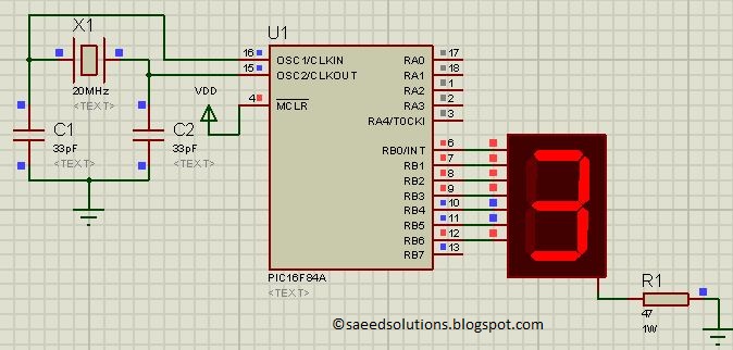
This post presents the implementation of a free-running counter using the C programming language for the PIC16F84A microcontroller. The code is structured to... The PIC16F84A microcontroller is a widely used device in various embedded applications, characterized by its 8-bit architecture...
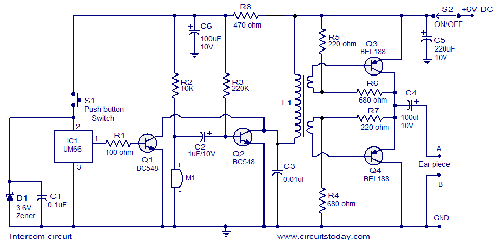
A straightforward intercom circuit designed using transistors. It does not require a changeover switch and can be used similarly to a telephone. This intercom circuit utilizes transistors to facilitate communication between two or more stations without the need for complex...

The fundamental digital circuits include Flip-Flops and Counters, both of which are present in this design. This circuit can be cascaded to create a six-digit event counter, and a simple frequency counter can also be constructed. Modern implementations are...
The output current of the control circuit must be amplified when the gate current needed to trigger the device exceeds the output current of the control circuit. To achieve the amplification of the control circuit output current, a suitable transistor...
This circuit measures the distance covered during a walk. The hardware is housed in a small box that fits into a pocket, and the display operates as follows: the leftmost display, D2 (the most significant digit), shows distances from...
This is a simple and cost-effective inverter designed to power a small soldering iron (25W, 35W, etc.) when a mains supply is not available. The circuit utilizes eight transistors along with several resistors and capacitors. Transistors Q1 and Q2,...
Warning: include(partials/cookie-banner.php): Failed to open stream: Permission denied in /var/www/html/nextgr/view-circuit.php on line 713
Warning: include(): Failed opening 'partials/cookie-banner.php' for inclusion (include_path='.:/usr/share/php') in /var/www/html/nextgr/view-circuit.php on line 713