
72 led clock
The clock circuit operates on a fundamental principle of digital electronics, where the 74HCT164 shift registers play a critical role in controlling the LED indicators. Each of the shift registers is capable of storing and shifting a single bit of information. By cascading eight of these registers, a total of 60 bits can be effectively managed, corresponding to the 60 minutes in an hour.
The circuit begins with a stable power supply that provides the necessary voltage and current for the LEDs and the logic components. The timing circuitry generates clock pulses that dictate the operation of the shift registers. Each pulse causes the data within the registers to shift, allowing the LEDs to illuminate sequentially, thereby indicating the passage of time.
For the hour display, a separate section of the circuit is dedicated to managing the 12 LEDs. This section can be designed using additional shift registers or a different logic configuration that accommodates the 12-hour format. The transition between minutes and hours is handled through a control mechanism, ensuring that as the minute count reaches 60, it resets and increments the hour count appropriately.
The overall design emphasizes efficiency and simplicity, utilizing readily available components. The cascading of shift registers not only allows for a compact design but also minimizes the number of required pins from the microcontroller or timer IC that drives the clock, thereby optimizing the circuit for space and power consumption. This modular approach also facilitates troubleshooting and future upgrades, as individual sections can be modified without impacting the entire system.
In conclusion, this clock circuit design effectively demonstrates the application of digital logic components in timekeeping, providing a clear visual representation of time through the use of LEDs while maintaining a straightforward and reliable operation.In the circuit, 60 individual LEDs are used to indicate the minutes of a clock and 12 LEDs indicate hours. The power supply and time base circuitry is the same as described in the 28 LED clock circuit above. The minutes section of the clock is comprised of eight 74HCT164 shift registers cascaded so that a single bit can be recirculated through the 60 stages indicating the appropriate minute of the hour..
🔗 External reference
Related Circuits
The mains supply can be conveniently reduced with no heat dissipation by the reactance of C1; then rectified by D1 (1N4007) and D2 (1N4007) and clamped to 24V. The circuit operates by utilizing the reactance of capacitor C1 to reduce...
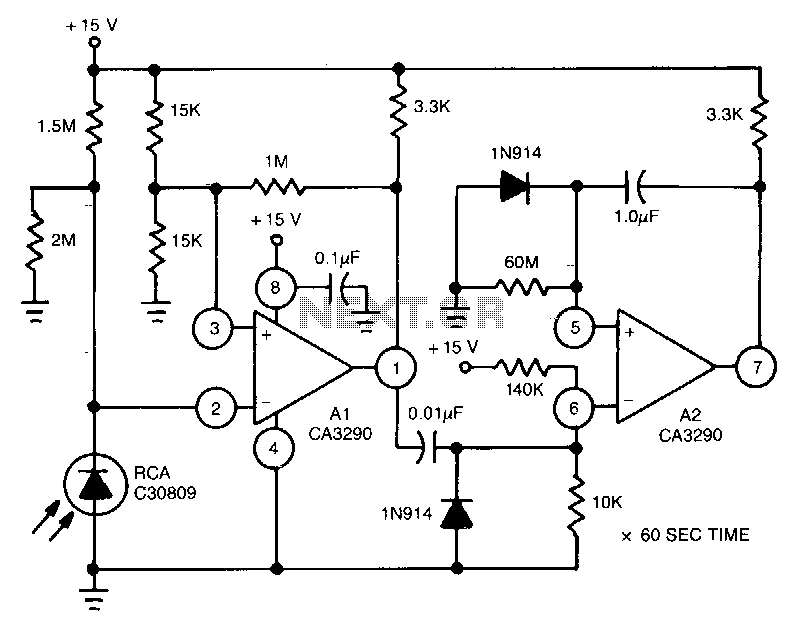
This circuit utilizes the CA3290 BiMOS dual voltage comparator to detect variations in the current of a light-emitting diode (LED). The output from the comparator triggers A2, a one-shot timer. If the light source to the photodiode is disrupted,...
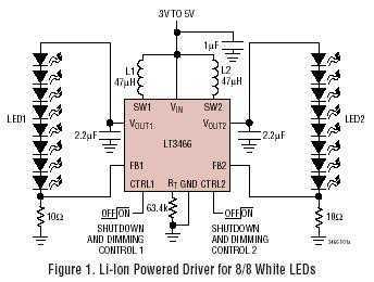
LT3466 is a dual full function step-up DC/DC converter specifically designed to drive up to 20 White LEDs (10 in series per converter) with a constant current. Series connection of the LEDs provides identical LED currents resulting in uniform...
This circuit diagram represents a radio-controlled system, commonly utilized in toy car applications for children. The circuit comprises two main components: the transmitter and the receiver circuits. The transmitter circuit generates radio signals through an oscillator circuit built with...
Loop stability analysis typically begins with an open-loop Bode plot of the system being examined, such as the power stage of a buck or flyback converter. This plot allows the designer to extract phase and gain information within the...
A schematic of a flip-flop LED flashing circuit is presented. This circuit functions as an astable multivibrator that activates LEDs sequentially upon power application. It is compatible with voltage inputs ranging from 6 to 12 volts, and can also...