
73 MHz Hallogene Lamp Radio-Controlled circuit
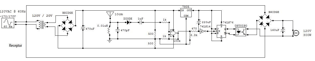
This radio-controlled halogen lamp circuit operates at a frequency of 73 MHz, allowing for effective remote control functionality. The remote control unit features a push button that, when activated, toggles the state of the lamp. The LED indicator on the remote control serves as a visual confirmation of the button press, indicating that a signal has been transmitted to the lamp controller.
The lamp controller circuit is designed to interface with a standard 120VAC power source, which powers the halogen lamp. The output of the controller circuit connects directly to the lamp, enabling it to receive power and respond to the control signals. The inclusion of antennas in both the remote control and the lamp controller ensures reliable communication, with the remote control transmitting commands to the receiver.
The circuit utilizes two critical logic components: the Schmitt trigger NOT gate (74LS14) and the JK Flip-Flop (74LS76). The Schmitt trigger is essential for signal conditioning, providing a clean transition between high and low states, thereby preventing false triggering due to noise. Its connection to the +5V regulator ensures stable operation. The JK Flip-Flop functions as a memory element, maintaining the state of the lamp based on the input from the remote control. Proper grounding and power supply connections for both components are crucial for the overall stability and functionality of the circuit.
In summary, the design of this radio-controlled halogen lamp circuit combines effective remote operation with reliable power control, utilizing essential logic components to ensure proper functionality and responsiveness.This circuit is a 73 MHz Hallogene Lamp Radio-Controlled. The purpose of it is to control the power state of a hallogene lamp by a remote control. When we press the push botton of the remonte control, the power state of the lamp will be changed, so, if the lamp was turned on, it will turned off and if it was turned on, it will turned off. If we pr ess to the button another time, the same action will be occured. When the button is pressed, a LED indicator lights on the remote control. The system is consisted by two separate circuit. One is the remote control, or the emmetor. The other is the receptor, or the hallogene lamp controller. We plug the input of the lamp controller circuit to the 120VAC source of the sector to supply it. The lamp must be pluged to the output of the circuit to be supplied and controlled. The controller circuit has also an antenna to receive the signal of the remote control. The remote control has also an antenna to transmit the signal to the controller circuit and have to be powered by a 9V battery. Two things important for my circuit are not mentioned in the schematic. There are about the two logic component. The first one is the Schmitt trigger NOT gate (74LS14). Its Vcc pin must be connected to the output of the +5V regulator (7805). And its GND pin must be connected to the ground of the circuit. The second one is the JK Flip-Flop (74LS76). Its Vcc pin must be connected to the output of the +5V regulator (7805). And its GND pin must be connected to the ground of the circuit. 🔗 External reference
Related Circuits
Q1 is a PNP power transistor used in conjunction with a ferrite transformer to form a blocking-type oscillator. This oscillator operates at a fixed frequency, with feedback for sustaining oscillations provided by capacitor C1. Due to the turns ratio...
This is a mini FM transmitter circuit that utilizes two transistors. The audio sensitivity is notably high when paired with an ECM type microphone. The transmitter operates using a Hartley oscillator configuration. Typically, the capacitor in the tank circuit...
A remote-controlled alarm circuit utilizing the TSOP1736 is designed for easy use by elderly individuals or patients confined to bed. This battery-operated alarm system eliminates the need for routing electric cables to a calling bell switch, making it a...
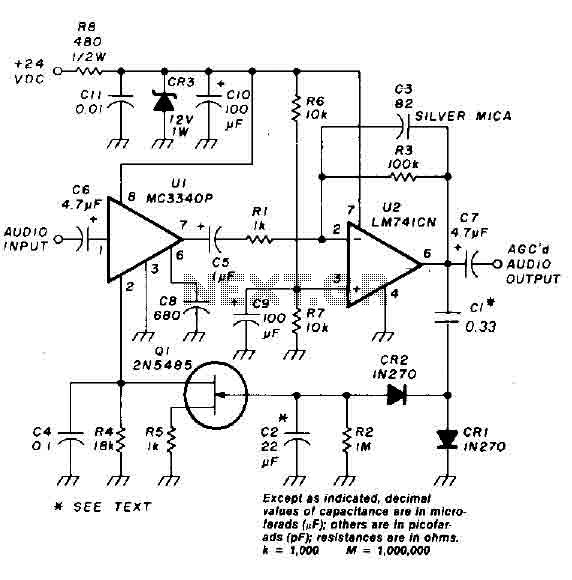
An audio signal applied to the input VI is passed through the operational amplifier 741, designated as U2. After amplification, the output signal V2 is sampled and sent to a negative voltage doubler/rectifier circuit composed of diodes CR1 and...
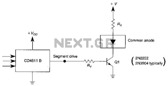
The use of a switching transistor, such as a 2N2222 or 2N3904, enables the operation of the CD4511B with a common-anode display. The transistor should be selected to provide approximately 1 mA to drive Q1, while resistor Rr must...
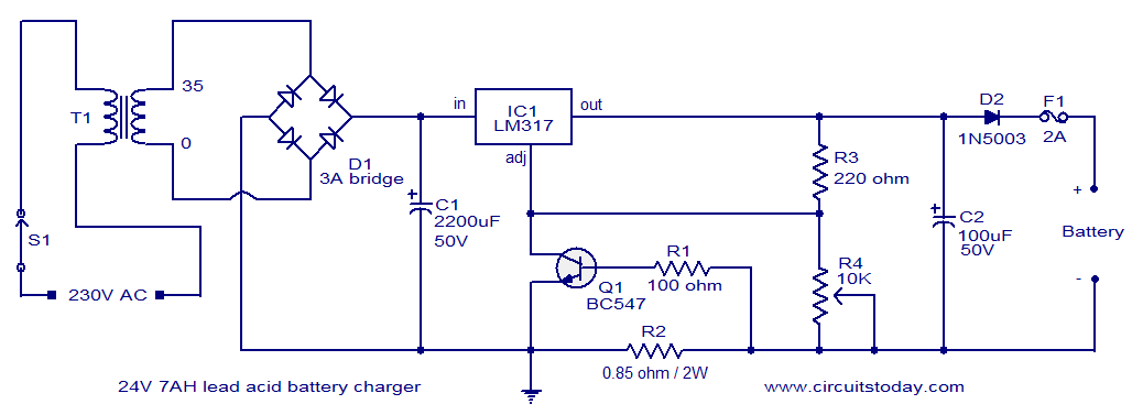
This lead-acid battery charger circuit is designed based on a request from Mr. Devdas C. His requirement was for a circuit that could charge two 12V/7AH lead-acid batteries connected in series. He did not specify the number of cells...