
75 impedance RF2320 linear amplification circuit diagram
The impedance linear amplifier circuit designed with the RF2320 is intended for applications requiring high fidelity and low distortion signal amplification. This circuit is particularly suitable for radio frequency (RF) applications where maintaining the integrity of the signal is crucial. The RF2320 is a versatile amplifier capable of providing a wide bandwidth and is optimized for 75-ohm systems, making it ideal for television and cable applications.
The circuit's layout typically includes two 75-ohm connectors, J1 and J2, which serve as the input and output ports, respectively. These connectors ensure that the amplifier is properly matched to the characteristic impedance of the transmission line, minimizing reflections and maximizing power transfer.
In operation, the RF2320 amplifies the input signal while maintaining a linear response across the desired frequency range. The design may include additional components such as resistors and capacitors to stabilize the amplifier, filter out unwanted frequencies, and enhance overall performance. Careful attention must be paid to the power supply and grounding arrangements to prevent noise and ensure optimal operation.
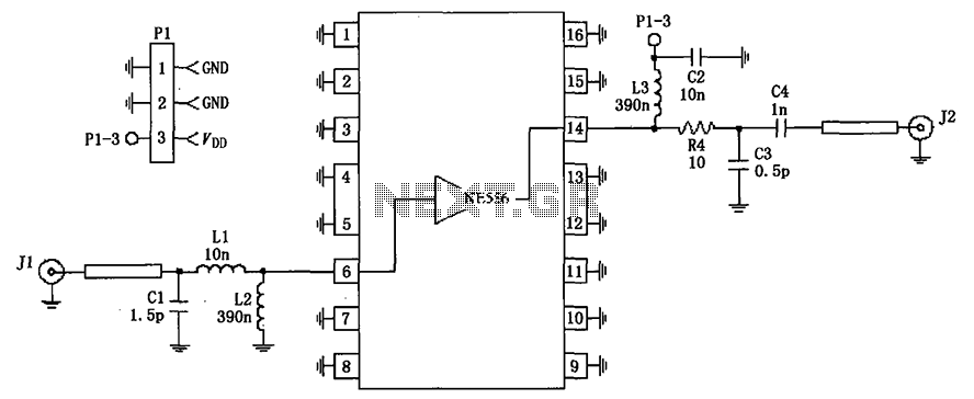
Overall, this impedance linear amplifier circuit is a critical component in RF signal processing, providing robust amplification while adhering to the necessary impedance standards for effective transmission and reception of signals. As shown in FIG 75 impedance linear amplifier circuit configured by RF2320. J1 and J2 are 75 F connector.
Related Circuits
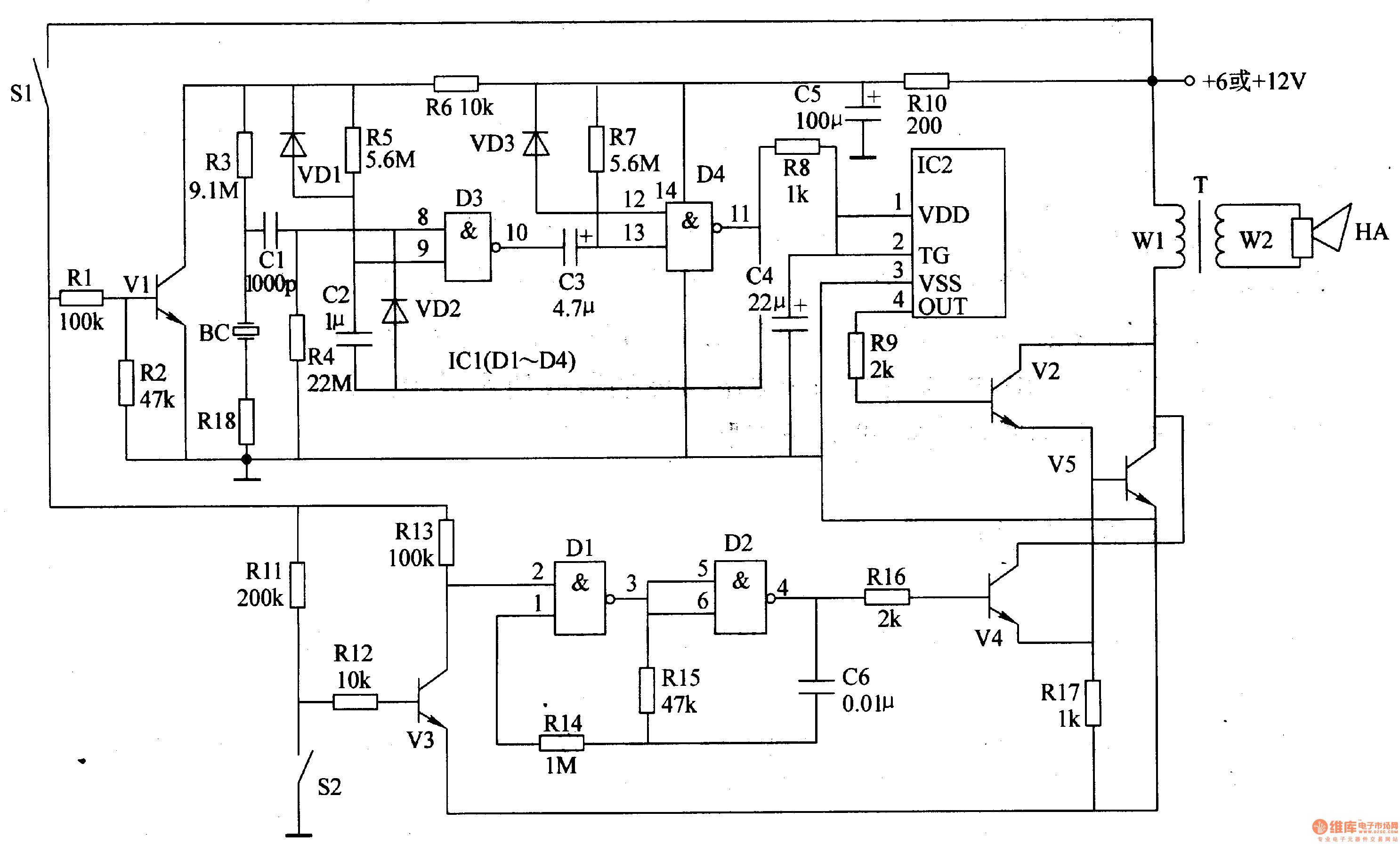
The motorcycle anti-theft alarm circuit consists of several components, including the anti-theft detection circuit, the control circuit, the sound generator, the audio oscillator, and the power amplifier output circuit, as illustrated in figure 7-91. The anti-theft detection circuit is...
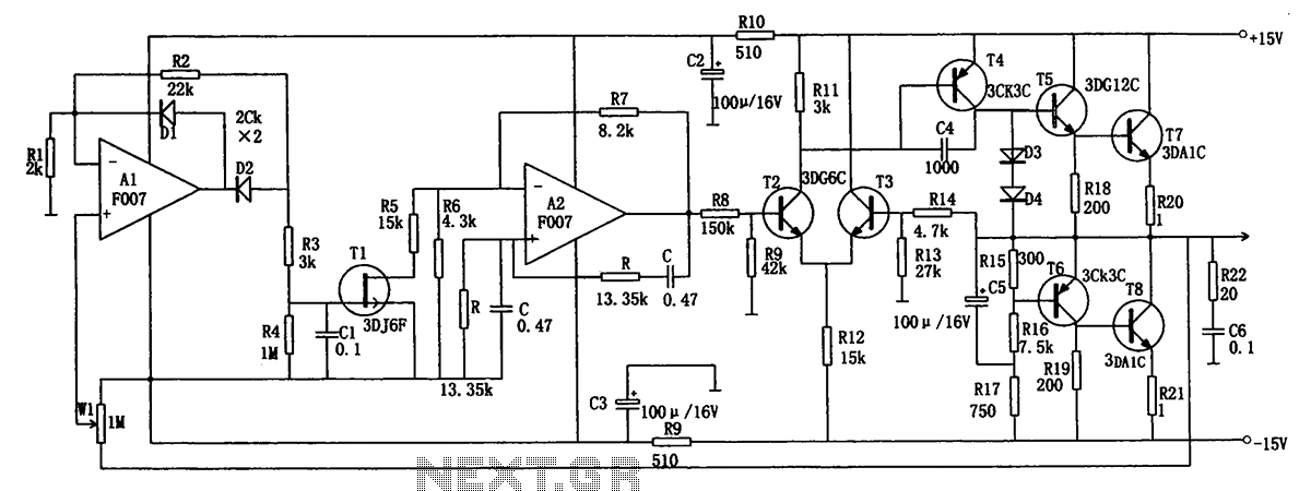
The low-frequency signal generating circuit demonstrates excellent performance characterized by stable operation, high output power, and minimal waveform distortion. It serves as an ideal source for low-frequency measurement signals. The circuit includes an operational amplifier (A) with a feedback...
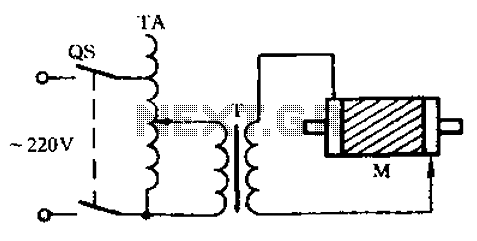
Check the three-phase motor with broken bars as shown in the inspection circuit for the three-phase motor with broken bars. The inspection circuit for a three-phase motor with broken bars is designed to diagnose and evaluate the condition of the...

When only the voltage regulator (VR) supplies power to the circuit, the microcontroller unit (MCU) will receive power from the +5V bus, while the FTDI chip will only receive VCCIO. At the midpoint of the voltage divider formed by...

The clock pulses from the 555 astable circuit are sent into the 4017 decade counter. Each output becomes high in turn as the clock pulses are received. Appropriate outputs are combined with diodes to supply the amber and green...
That circuit is based at a technique to remove or neutralize the salt in water, and protect the pipes at home as well as the washing machines or our selves from salt. Its called water softener and its automated...