
7809 Pin and

The 7809 voltage regulator is designed to provide a stable output voltage in various electronic applications. Its compact size and ease of integration make it a preferred choice for many designers. The three-pin configuration allows for straightforward connections: the input pin accepts the unregulated voltage, the output pin delivers the regulated voltage, and the ground pin serves as the reference point.
For optimal performance, the inclusion of input and output capacitors is advisable. These capacitors help to smooth out voltage fluctuations and ensure that the regulator operates effectively under varying load conditions. The typical values of 1µF for both capacitors are commonly recommended, although larger capacitance values may be used in applications requiring greater stability.
In terms of thermal management, it is crucial to consider the heat generated by the 7809 during operation, especially when operating at higher loads. The use of a suitable heat sink will increase the thermal dissipation capacity, thus prolonging the lifespan of the IC. The selection of fuses is also critical; using a 1A fuse on the output side will protect downstream components from overcurrent conditions, while a 1.5A fuse on the input side will safeguard the circuit from excessive input current, which can be caused by short circuits or component failures.
The 7809 is part of a family of voltage regulators (LM78XX series), which includes other models such as the 7812, which provides a regulated 12V output. These regulators share a similar pin configuration, making them interchangeable in many designs. Understanding the specifications and limitations of the 7809 is essential for its effective application in circuit designs, ensuring reliability and performance in voltage regulation tasks.7809 is a voltage regulator integrated circuit(IC) which is widely used in electronic circuits. Voltage regulator circuit can be manually built using parts available in the market but it will take a lot of time to assemble those parts on a PCB. Secondly, the cost of those parts is almost equal to the price of 7809 itself so professionals usually p
refer to use 7809 IC instead of making a voltage regulator circuit from scratch. Before you start using 7809, you will need to know about the pin structure of IC 7809. Apparently, it looks like a transistor. It has three pins. For a better understanding, I have given an image of 7809 bellow. Please take a look. You can easily see the V in and V out pins as well as the ground pin. It is really easy to use 7809 for voltage regulation purposes. I have also included a circuit diagram of 7809 so that you may learn how to use it in a circuit diagram. It is wise to use two. 1uF capacitors on both input and output sides to filter any ripple or distortion in voltage but it is not necessary.
In the image, you can see that 12V are being supplied on the input side of 7809 but the out put side of 7809 is outputting Regulated 9V. As long as the input voltage remains above 9V, output voltage of 7809 will remain smooth and regulated.
Please note that input voltage of 7809 can be up to 23V but under my experience, it is wise to avoid input over 15V. 7809 is claimed to output 9V and almost 1. 5A Current but again, I have experienced that we should not put a load over 9V and 1A on it. Since we are using it in power supply, the transfer of power will result in heat output. We will need to use a heat sink with 7809 otherwise this heat can damage it. It is advised to use a 1A fuse on the output side of 7809 and a 1. 5A fuse on the input side of 7809 to avoid damage in case of short circuit. Thanks for the 7809 pinout information. Your diagrams really helped me in understanding 7809 pinout. Can you please tell me if 7812 also has same pinout configuration Thanks for you diagram on the 7809 IC, it has helped me in my project work.
I am also having some Challenges concerning the tuning my inverter. I am having a a very high frequency around 11. o5 MHz, I was expecting 50Hz please how do i go by it. The inverter is a 500W inverter diagram on. Pleas help me out For the question regarding the use of capacitors with the LM78XX (LM7809 in this case): The capacitors are used as a filter and stablizer for more consistant input and output of the regulator. It is suggested in virtually all applications and, is recommended by most LM78XX manufacturers. As stated in the opening of this page, it can be used without the capacitors in applications were consistancy is not requirement, such as running low draw fans or incandescent bulbs that can handle fluxuations.
Thank you very much! A man like me who never made any such thing managed to connect my D-battery powered radio to a 12V truck battery at first attempt. Simple and easy, much appreciated. it is very simple ckt but when power will come how it will work and how battery gets charge, kindly clear.
i want to use in main line to use it when ever power goes it should be automaic on and whenever comes it should be off. 🔗 External reference
Related Circuits
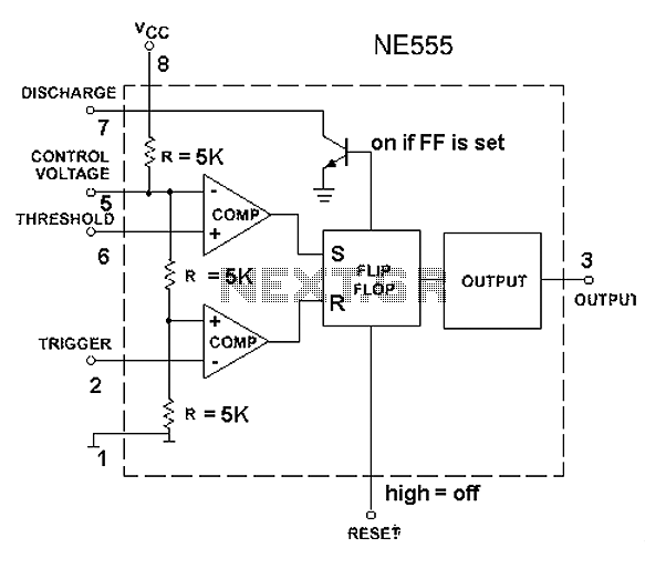
The 555 timer circuit, regardless of the manufacturer, has a consistent internal structure and performance. Various manufacturers produce different models of the 555 timer, including MC555, CA555, XR555, LM555, as well as domestic models like SL555, FX555, and 5G1555....
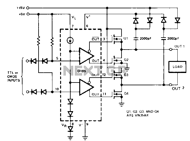
When driving MOSPOWER in a totem-pole output configuration, it is essential to maintain a gate voltage of 10 to 15 V positive relative to the source to manage load currents close to the maximum ratings of the MOSPOWER device....
The circuit generates geomagnetic fields that allow for their perception, creating an ideal environment for sound sleep. When SW2 is open (Alternate mode operation), the device operates for a pre-set duration and then pauses for the same amount of...
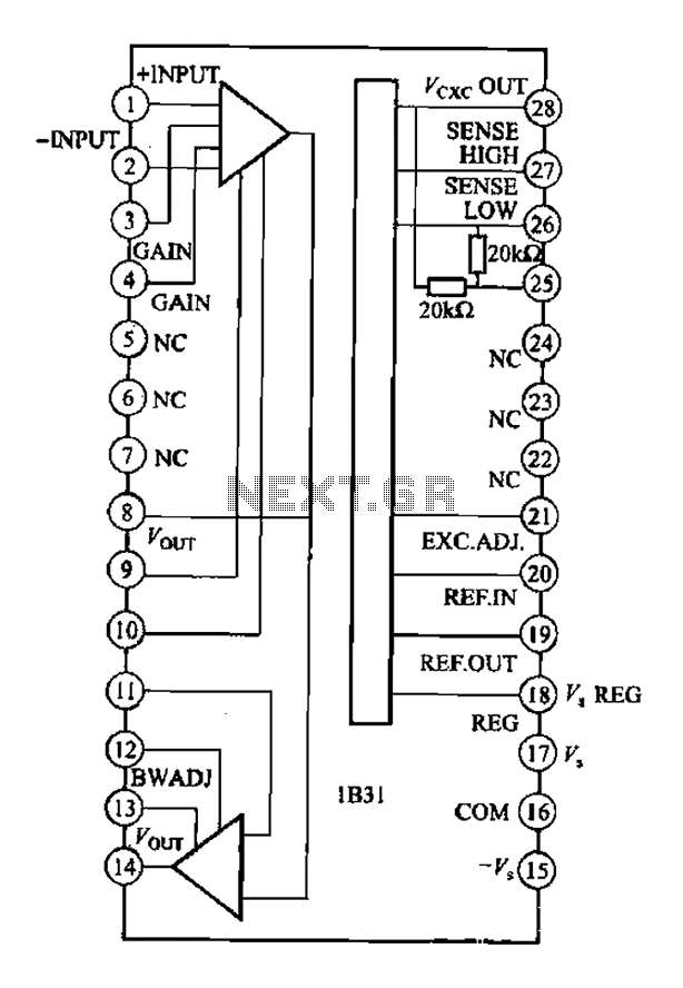
The Analog Devices 1831 is designed for strain gauge signal conditioning applications. It features an internal low drift input of 0.25V with a gain of 1000, exhibiting excellent linearity with a maximum deviation of 0.005%. The IC operates with...
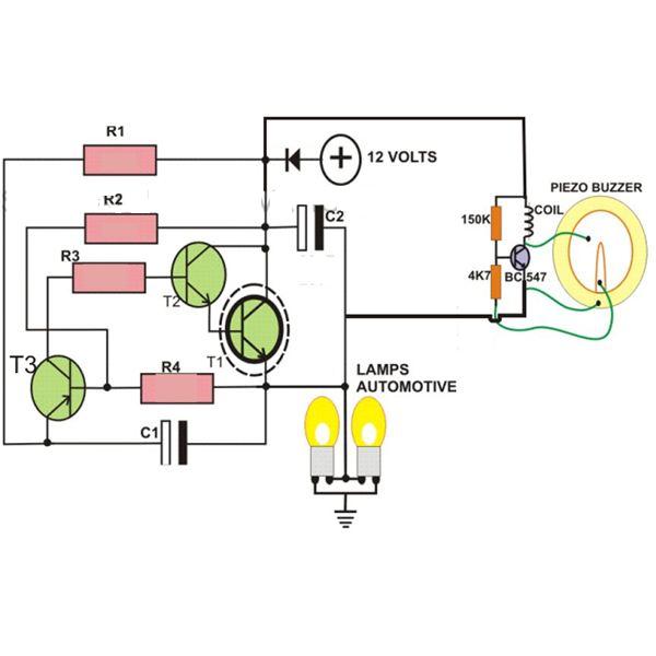
This circuit is designed to create a flasher unit for a motorbike. It is a simple turn signal flasher circuit that can be easily built and installed in any two-wheeler for the desired functionality. The circuit uses only two...
The amplifier in the following schematic, when simulated, demonstrates the ability to effectively amplify a signal with an amplitude of 0.1V to 10V. However, when subjected to a larger input signal, the performance deteriorates significantly during the positive half...