
78XX Voltage Regulator Extension
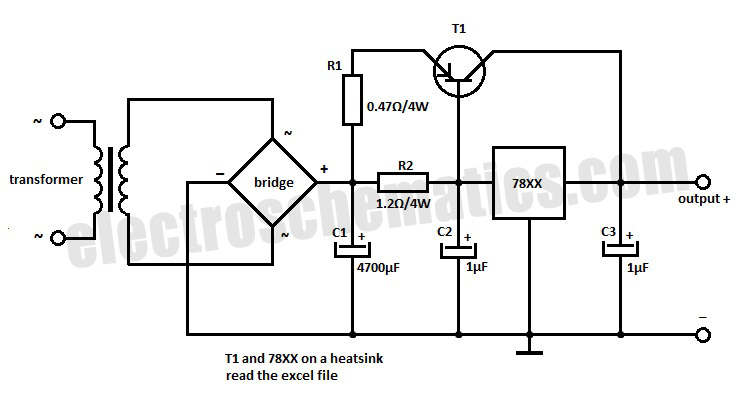
This voltage regulator extension circuit is designed to enhance the output current capacity of a standard voltage regulator, enabling it to supply up to 10 A. The main component, T1, is a power transistor that plays a critical role in this circuit. It operates in conjunction with a resistor placed in the emitter leg, which serves to stabilize the transistor's operation and improve linearity.
The circuit typically includes additional components such as capacitors for input and output filtering, ensuring stable voltage levels and minimizing ripple. A diode may also be included for protection against reverse polarity, which can safeguard the circuit from potential damage.
The design necessitates careful selection of the power transistor, as it must be capable of handling the increased current without overheating. Adequate heat sinking is essential to dissipate the heat generated during operation, ensuring reliable performance over extended periods.
Moreover, the circuit may incorporate feedback mechanisms to maintain voltage regulation under varying load conditions. This can involve additional resistors and operational amplifiers to create a closed-loop system that adjusts the output voltage dynamically based on the load demand.
In summary, this voltage regulator extension circuit is a robust solution for applications requiring higher current outputs, featuring a power transistor with an emitter resistor to enhance stability and performance, along with essential components for filtering and protection.With this voltage regulator extension circuit you can increase the output current up to 10 A. T1 power transistor has a resistor in the emitter and thus th.. 🔗 External reference
Related Circuits
Mode control of the average current (CMC) is necessary to regulate the overall waveform of electric current during the rebuilding cycle. This text recommends selecting specific parameters related to the voltage transformer and outlines steps for designing a circuit...
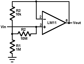
This circuit utilizes an LM11 operational amplifier configured as a voltage follower with an input resistance of 1 GΩ, constructed using standard resistor values. When the input is left disconnected, the input offset voltage is amplified by the same...
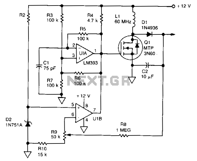
U1 is a dual voltage comparator with open collector outputs. The A side functions as an oscillator operating at 100 kHz, while the B side is part of the regulation circuit that compares a fraction of the output voltage...
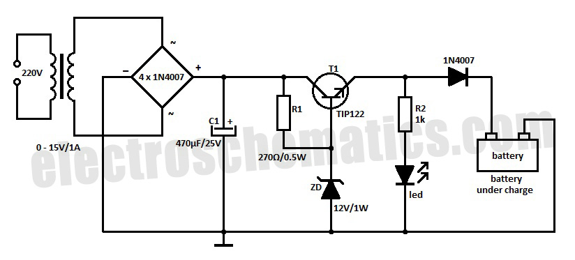
Most battery chargers lack provisions for current and voltage regulation. The step-down voltage is primarily utilized for charging purposes. Many battery chargers operate on a straightforward principle of reducing the input voltage to a level suitable for charging a battery....
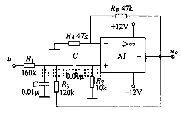
A band-pass filter permits only signals within a specified frequency range to pass through, while attenuating or suppressing those outside this range. This is characterized by a lower frequency limit and an upper frequency limit. A typical implementation is...
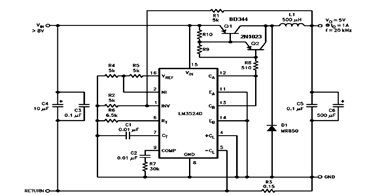
The schematic diagram below illustrates a 5V/1A Step-Down Switching Regulator utilizing the LM2524D Regulating Pulse Width Modulator (PWM). Additional parameters, PC board layout, stuffing diagram, and more information can be found in the LM2524D datasheet. The circuit design features the...