
2 LED Flasher with 555
Part List
R1-2= 1.5Kohm C2= 100nF 63V D1-2= LED 3mm
R3= 250Kohm trimmer C3= 100uF 16V BATT= 9V Battery
R4-5= 470 ohm IC1= 555 S1= Push Button or switch on-off
C1= 10uF 16V IC2-3= 4N25 optocoupler
The circuit described utilizes a 555 timer IC (IC1) configured in astable mode to produce a square wave output, which drives two light-emitting diodes (D1 and D2). These LEDs can be of different colors, providing visual indication through alternating flashes. The frequency of the flashing can be adjusted using a variable resistor (R3), which is a 250K ohm trimmer potentiometer, in combination with the timing capacitor (C1, 10uF). Adjusting the capacitance of C1 will directly influence the frequency of the output pulses.
The circuit can be powered by a 9V battery or an external power supply, allowing for flexibility in its application. The design can serve as an alarm indicator, where the alternating LEDs act as a visual cue for an alert condition.
Additionally, the circuit includes two optocouplers (IC2-3, 4N25), which can be connected in parallel with the LEDs. This feature allows the circuit to interface with other electronic systems or circuits, enabling the external control of various devices in response to the flashing LEDs. The use of optocouplers enhances the circuit's versatility, enabling it to drive higher power loads or isolated circuits without direct electrical connection.
The resistors (R1 and R2, each 1.5K ohm, and R4 and R5, each 470 ohm) are used to limit the current flowing through the LEDs, ensuring they operate within safe limits. The capacitor (C2, 100nF) provides additional stability in the timing circuit, while the larger capacitor (C3, 100uF) may serve as a power supply filter to ensure stable operation during transient conditions.
Overall, this circuit is a simple yet effective design for creating alternating LED signals, with the potential for integration into larger systems or applications requiring visual alerts. The circuit is based on the IC1 that is 555, for the creation of alternate flashes from the two led D1-2, that can be also different colour. The frequency of alternation can be regulated from the trimmer R3 and from the C1, if changes his capacity.
The supply can become from a battery or from one separate power supply. A use of circuit is creation '' clue '' of alarm. Exists the possibility is connected at the same time with D1-2, the optocoupler IC2-3, with that we externally drive circuits, for various uses. Part List R1-2= 1.5Kohm C2= 100nF 63V D1-2= LED 3mm R3= 250Kohm trimmer C3= 100uF 16V BATT= 9V Battery R4-5= 470 ohm IC1= 555 S1= Push Button or switch on-off C1= 10uF 16V IC2-3= 4N25 optocoupler 🔗 External reference
Related Circuits
Twelve LEDs can be arranged in a circle to represent the twelve hours of a clock face, while an additional twelve LEDs can be arranged in an outer circle to indicate five-minute intervals within the hour. Four additional LEDs...
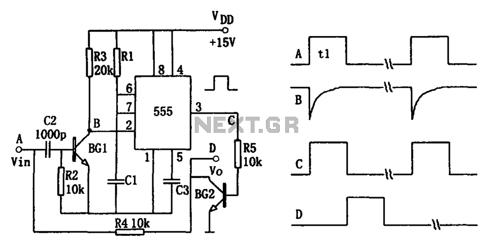
The pulse-width detection circuit is illustrated in the figure and consists of a differential circuit (R2, C2), an amplifier (BG1), a single stabilizing circuit (555, R1, C1), and various other components. The pulse signal Vin (depicted as waveform A)...
The circuit employs 60 individual LEDs to represent the minutes of a clock and 12 LEDs to indicate the hours. The power supply and time base circuitry are consistent with those described in the previous 28 LED clock circuit....
This LED flasher circuit is similar to the previous transistor-based LED flasher but utilizes a 555 integrated circuit as the primary component. The schematic diagram illustrates an LED flasher circuit that produces alternating LED flashing, with distinct flashing periods...
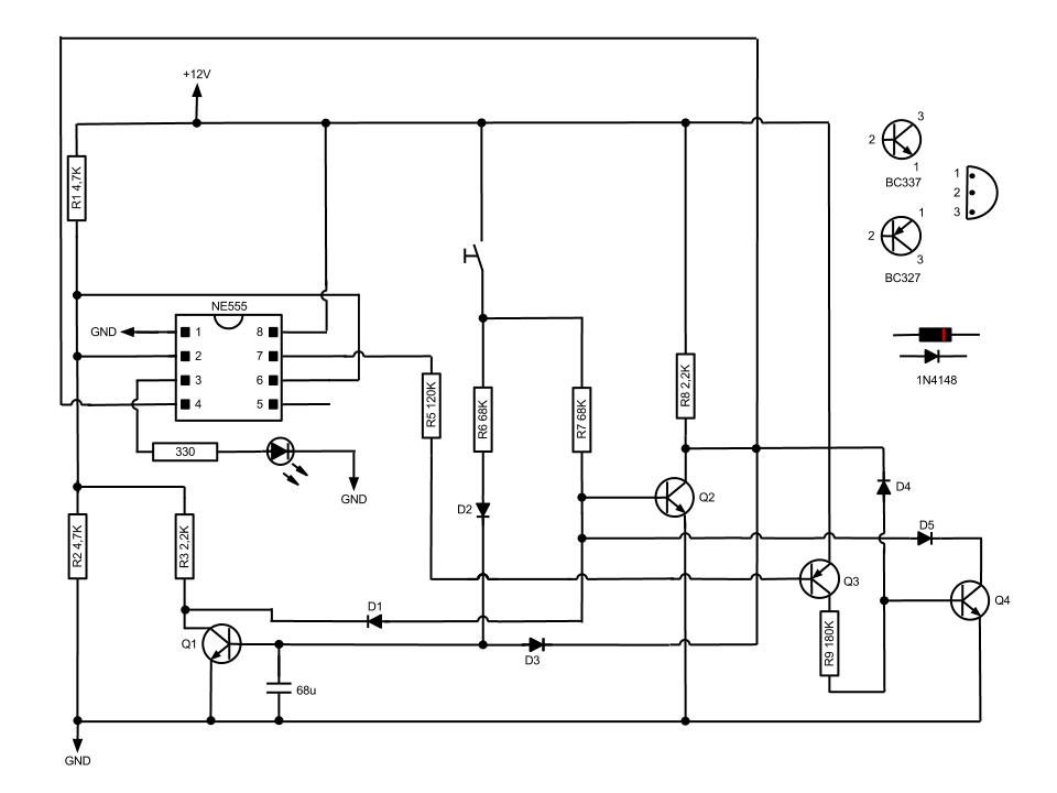
This circuit, based on the NE555 timer IC, toggles the output on and off using a momentary switch. It functions similarly to a mechanical latching relay but resets to its initial state when the power supply is turned off....
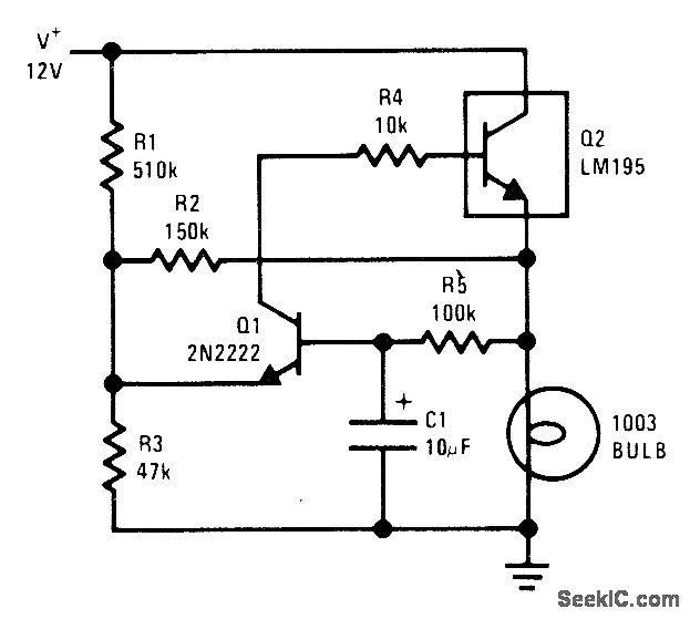
The National LM195 power transistor is activated and deactivated once per second to flash a 12-V lamp. The current limiting feature of the LM195 prevents high peak currents during turn-on, even when a cold lamp can draw up to...
Warning: include(partials/cookie-banner.php): Failed to open stream: Permission denied in /var/www/html/nextgr/view-circuit.php on line 713
Warning: include(): Failed opening 'partials/cookie-banner.php' for inclusion (include_path='.:/usr/share/php') in /var/www/html/nextgr/view-circuit.php on line 713