
8 Pin PIC12C508A and PIC16F84 programmer circuit
The circuit designed for programming the PIC12c508A and PIC16F84 microcontrollers utilizes a standard IC programming approach, which allows for flexibility in programming various microcontrollers within the specified pin configurations. The programming interface typically includes a series of connections that link the programmer to the target microcontroller, ensuring proper communication and power supply during the programming process.
Key components of the circuit include a microcontroller programmer, which serves as the central unit for controlling the programming sequence. The programmer interfaces with a host computer via USB or serial communication, allowing the user to upload firmware or configuration files. The programmer’s firmware must be compatible with the IC-Prog software, which provides a user-friendly interface for selecting the target microcontroller and managing the programming operations.
The circuit also incorporates level shifters or voltage regulators to ensure that the programming voltage levels are compatible with the target microcontrollers, as different microcontrollers may operate at different voltage levels. For instance, the PIC12c508A typically operates at 5V, while some other microcontrollers might require lower voltage levels, necessitating the use of appropriate voltage conversion components.
Additionally, the schematic will include necessary connections for programming pins such as MCLR (Master Clear), PGD (Program Data), and PGC (Program Clock). These pins are essential for the programming process, allowing the programmer to send and receive data from the microcontroller. Pull-up resistors may be included on the MCLR pin to ensure proper reset behavior during programming.
To enhance reliability, decoupling capacitors should be placed near the power supply pins of the microcontroller to filter out noise and stabilize the supply voltage during operation. The layout should also consider trace lengths and widths to minimize inductance and resistance, which can affect the programming signal integrity.
In conclusion, this programming circuit is designed to be versatile and efficient, supporting various 8-pin and 18-pin microcontrollers while ensuring adherence to the specifications required for successful programming. The use of established programming protocols and careful circuit design will result in a robust solution for microcontroller programming needs.This project is designed to program the 8-pin PIC12c508A and 18pin PIC16F84 microcontroller chips to support the projects we have designed, however it will also program a number of other 8-pin & 18-pin microcontrollers and the full list can be seen when using IC-Prog. 🔗 External reference
Related Circuits
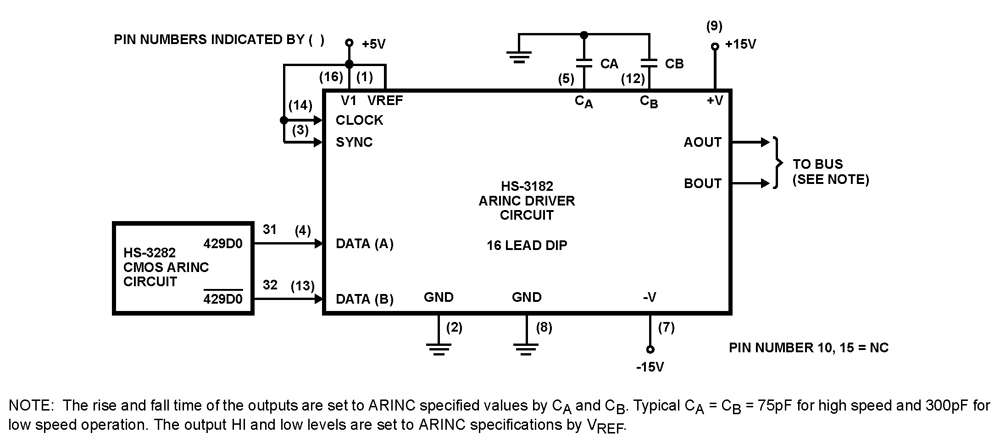
The HS-3182 is a monolithic dielectrically isolated bipolar differential line driver designed to meet the specifications of ARINC 429. This device is intended to be used with a companion chip, the HS-3282 CMOS ARINC Bus Interface Circuit, which provides...
Both circuits are designed solely for overcurrent protection in power supply applications. The circuits in question serve as critical components in safeguarding power supply systems from overcurrent conditions. Overcurrent protection is essential in preventing damage to electrical components and...
Hello everyone, I am not well-versed in electronics, so I would appreciate it if someone could create a diagram for me. I would like to modify a circuit so that it can dial a number using speed dial and...
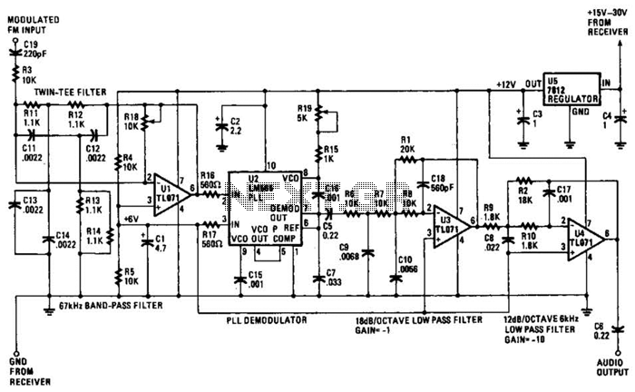
The operational amplifier (Op Amp) U1 and its associated components form a 67-kHz bandpass filter. A twin-T network, consisting of four 1100-ohm resistors and four 0.0022-microfarad capacitors, is integrated into the feedback loop of the op amp. This configuration...
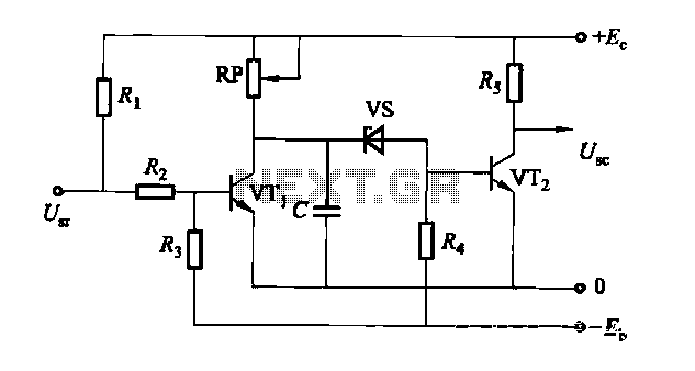
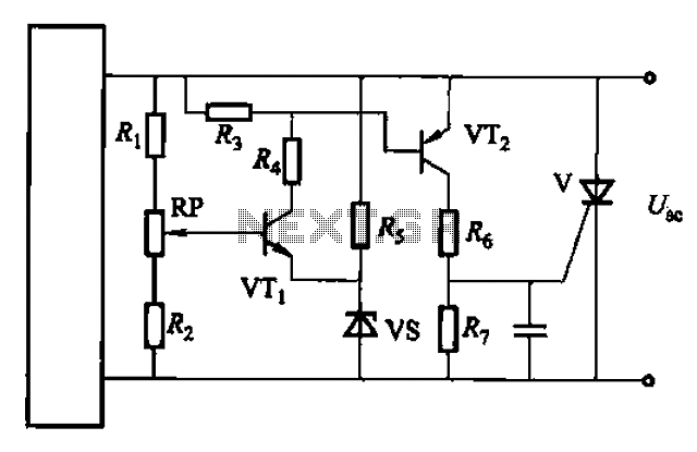
The circuit is a rechargeable short delay control for a conducting pipe, featuring two adjustment potentiometers (RP) that enable the delay time to be set from several hundred milliseconds to several seconds. The rechargeable short delay circuit is designed for...
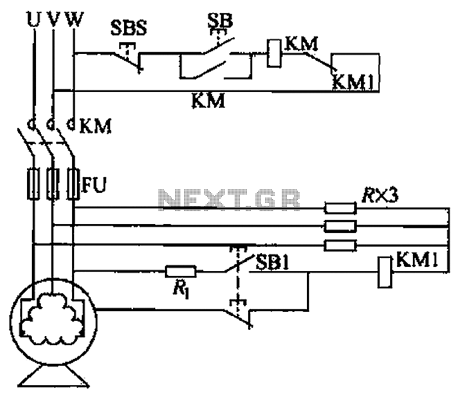
A voltage leakage protection circuit utilizing a resistive element as an auxiliary neutral point is illustrated in the accompanying figure. When selecting the resistance, it is essential to consider both the resistance value and power consistency. The described voltage leakage...
Warning: include(partials/cookie-banner.php): Failed to open stream: Permission denied in /var/www/html/nextgr/view-circuit.php on line 713
Warning: include(): Failed opening 'partials/cookie-banner.php' for inclusion (include_path='.:/usr/share/php') in /var/www/html/nextgr/view-circuit.php on line 713