
800W high power mosfet amplifier Schematic Diagram
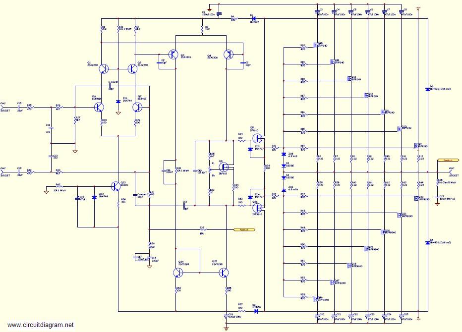
The 800W high power MOSFET amplifier circuit is designed to deliver robust audio performance with an emphasis on efficiency and fidelity. The amplifier utilizes MOSFET transistors, known for their high input impedance and fast switching capabilities, which contribute to the overall low distortion and high power output.
The schematic diagram illustrates the various components and their interconnections, including the input stage, gain stage, output stage, and feedback mechanism. The input stage typically consists of a differential amplifier configuration, which helps to amplify the audio signal while minimizing noise. The gain stage further increases the signal level, ensuring sufficient power is available for the output stage.
The output stage is where the MOSFETs come into play. These transistors are arranged in a push-pull configuration to efficiently drive the load, which could be a speaker or a series of speakers in a surround sound setup. The use of MOSFETs allows for high current handling and thermal stability, making the amplifier suitable for demanding applications like subwoofers and large PA systems.
Power supply considerations are crucial for the performance of this amplifier. A robust power supply is necessary to provide the required voltage and current levels, ensuring that the amplifier can operate at its full capacity without distortion. The power supply circuit typically includes filtering capacitors to smooth out voltage fluctuations and provide stable operation.
The complete component listing includes specifications for each component, such as resistors, capacitors, and the MOSFETs themselves, allowing for easy replication of the circuit. This detailed documentation serves as a valuable resource for engineers and hobbyists looking to build or modify high-power audio amplifiers.
In summary, the 800W high power MOSFET amplifier circuit is a versatile and powerful solution for high-performance audio applications, combining advanced circuit design with high-quality components to achieve outstanding sound reproduction.This amplifier can be used for practically any application that requires high power, low noise, distortion and excellent sound. Examples would be Sub-woofer amp, FOH stage amplifier, One channel of a very high-powered surround sound amplifier etc.
For detail explanation about how this circuit works include the large schematic diagram, power supply schematic diagram and complete component listing, link download this complete article. You are reading the Circuits of 800W high power mosfet amplifier And this circuit permalink url it is 🔗 External reference
Related Circuits
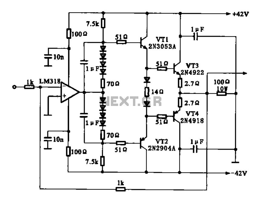
The current amplifier circuit configuration is illustrated in the figure. It consists of a two-stage operational amplifier, the LM318, arranged in a complementary push-pull amplifier configuration, which exhibits low output resistance and possesses load capacity features. The current amplifier circuit...
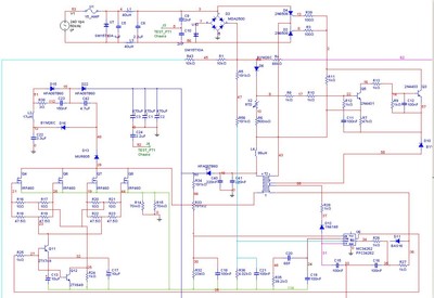
A Power Factor Correction (PFC) board has been obtained from an old Sun Microsystems Spark450 power supply (part number 300-1359-xx). This board contains all necessary components for a 650-watt inverter. However, the complete PFC circuit is not fully detailed...
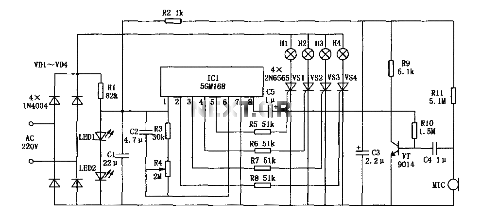
This document describes a family karaoke lighting design that employs various methods to control the circuit. The control circuit presented here features a four-way light output with loop jumping and speed control capabilities. The practical circuit utilizes a microphone...
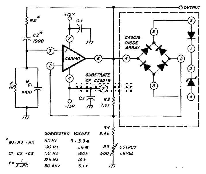
The circuit diagram utilizes a CA3140 operational amplifier and a diode array to generate a low distortion sine wave. A table specifies the values of resistors (R) and capacitors (C), enabling frequency access ranging from 50 Hz to 30...
The circuit is simple, yet capable of excellent performance. It is designed specifically for use as an amplifier for the digital sound card in a computer. Audio input can be sourced from any two-channel line level device, such as...
The 2SK2975 has reportedly been discontinued by the manufacturer, with the RD07MVS1 from Mitsubishi serving as its replacement. This new device is very similar but appears to have slightly higher gain—10 dB typical at 520 MHz compared to 8.4...
Warning: include(partials/cookie-banner.php): Failed to open stream: Permission denied in /var/www/html/nextgr/view-circuit.php on line 713
Warning: include(): Failed opening 'partials/cookie-banner.php' for inclusion (include_path='.:/usr/share/php') in /var/www/html/nextgr/view-circuit.php on line 713