
80x32 LED matrix display
The LEDMATRIX additionally includes a simple speaker allowing notifications for new messages being displayed. Furthermore, a TSOP1736 IR receiver can optionally be connected. This device receives and decodes the IR signals used by ordinary TV remote controls. By returning information about received IR signals to the controlling PC, the display's contents may be remotely changed using a simple spare IR remote control. With one display drawing 2A @ 5V, the power supply of the LEDMATRIX needs to source all ten displays and thus needs to be able to provide a total current of 20A. A cheap old PC power supply that delivers 20A on the 5V line may be sufficient. A Lambda UAZ1G 30A power supply is used, which has been modified by replacing the noisy small fan with a very quiet 70mm one. There is much unused space in this power supply, so the fan can easily be replaced with a bigger one, and adding a power switch and a connector for a standard power supply cable is not a problem. Even with the fan completely switched off and with the display at full amber brightness (all 5120 LEDs switched on), the power supply barely gets warm. This whole project is open under the GPL, providing full access to the firmware source code, schematics, and PC companion software.
The LED matrix display units, SLM1608 (SLM1606), are designed for flexible and vibrant visual output, featuring an arrangement of 16x16 LEDs per unit, capable of displaying various colors through the combination of red and green LEDs. Each unit's integrated controller simplifies the data management process, allowing for efficient multiplexing of signals. This enables the configuration of an expansive 80x32 pixel display by arranging ten units in a two-row setup, facilitating real-time updates and control through a microcontroller such as the ATmega32.
The utilization of an Ethernet interface, powered by the Cirrus Logic CS8900 chip, significantly enhances the data transfer rate compared to traditional RS232 methods, accommodating rapid graphical updates. The project also incorporates an audio notification system via a simple speaker and includes an optional TSOP1736 IR receiver module for remote control capabilities, enhancing user interaction.
Power management is a critical aspect of this design, necessitating a robust power supply capable of delivering 20A at 5V to support the full brightness of the display. The Lambda UAZ1G power supply serves this purpose effectively, with modifications made to improve acoustic performance and usability. The project remains open-source under the GPL, promoting collaborative development and access to resources for further enhancements and modifications.I recently purchased 10 SLM1608 (SLM1606) LED matrix display units from Ebay (you might also contact the seller directly at [email protected]). These are 16x16 LED matrix units with a green and a red LED per pixel allowing each pixel to be switched to either green, red, amber or off.
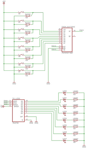
The goal of this LEDMATRIX project was to build a 80x32 pixel display by arranging the displays in two rows with 5 displays each giving a total of 16*16*2*2*5 = 5120 LEDs to be controlled individually. Fortunately these displays come with interated controllers and the data can be shifted into a single display using as few as 6 digital signals.
By multiplexing some of the select signals all 10 displays can be controlled with a total of ten wires. Using a cheap ATmega32 microcontroller all ten displays can easily be controlled and updated in real time.
This kind of display is usually controlled via RS232. This has the disadvantage of being very slow and the display data is limited to simple text messages only with the microcontroller of the display doing the actual text drawing. Instead of doing it the same way i decided to use an ethernet interface for the LEDMATRIX display. Even the most simple ethernet interface i am using is fast enough to transfer graphics data in realtime from a PC to the display allowing to update the entire screen 50 times a second.
The ethernet support of LEDMATRIX is based on the cirrus logic cs8900 chip which is e.g. supported by the free Procyon AVRlib which has been used for this project. The LEDMATRIX additionally includes a simple speaker allowing to e.g. notify the user of a new message being displayed. Furthermore a TSOP1736 IR receiver can optionally be connected. This device receives and decodes the IR signals used by ordinary TV remote controls. By returning informtion about received IR signals to the controlling PC, the displays contents may e.g. be remotely changed using a simple spare IR remote control. With one display drawing 2A @ 5V, the power supply of the LEDMATRIX needs to source all ten displays and thus needs to be able to provide a total current of 20A.
You might be able to find a cheap old PC power supply that delivers 20A on the 5V line. I am using a Lambda UAZ1G 30A power supply. I made some small modifications to the device. I e.g. replaced the noisy small fan with a very quiet 70mm one. There's much unused space in this power supply so the fan can easily be replaced with a bigger one and e.g. adding a power switch and a connector for a standard power supply cable isn't a problem. Even with the fan completely switched off and with the display at full amber brightness (all 5120 LEDs switched on) the power supply barely gets warm.
This whole project is open under the GPL. This means that you get full access to the firmware source code as well as to the schematics and the PC companion software. 🔗 External reference
Related Circuits
The circuit consists of two stages. The first stage is a switch or cut-off device. It detects a voltage above 0.7V from the solar panel, and the resistance between its collector-emitter terminals reduces to a very small value. The...
This circuit utilizes a JFET to receive signals from an LED and buffer them. The output voltage is managed using an IC 1458 or LM1458, which provides approximately 7 volts in darkness and experiences a drop of about 2...
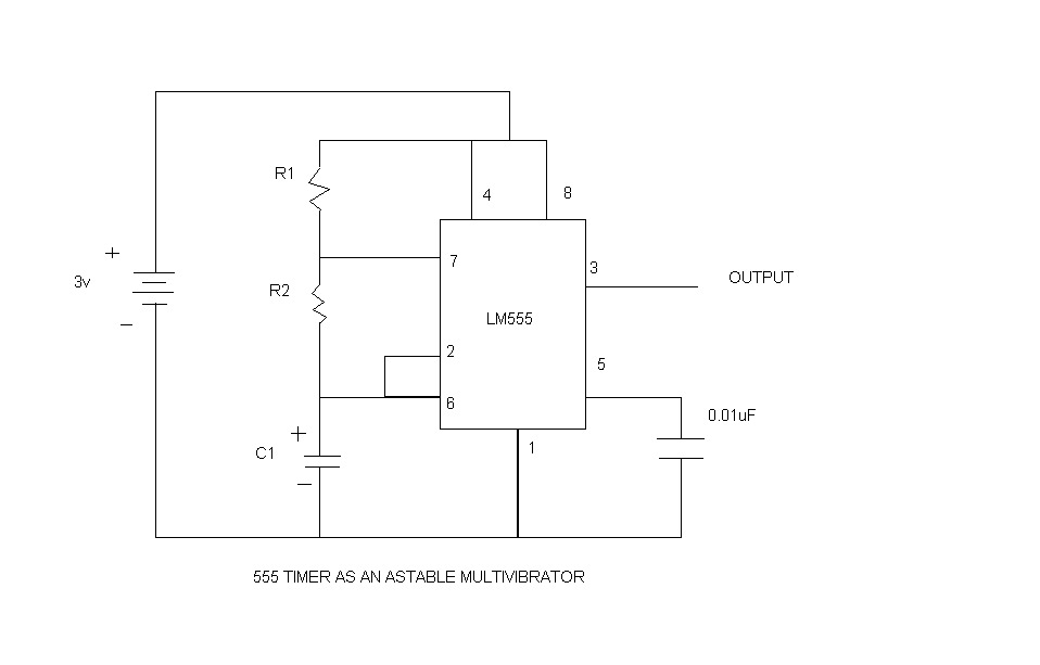
An astable multivibrator, commonly referred to as a free-running multivibrator, is a circuit that generates rectangular waves without the need for external triggering. The timing characteristics of this circuit are determined by the values of the resistors and capacitors...
To enable the MonomeSerial software to recognize the monome clone, it is necessary to modify the Arduino's EEPROM serial number to match that of a genuine monome. Following Melka's updated instructions from the Bricktable blog is recommended. The D2XX...
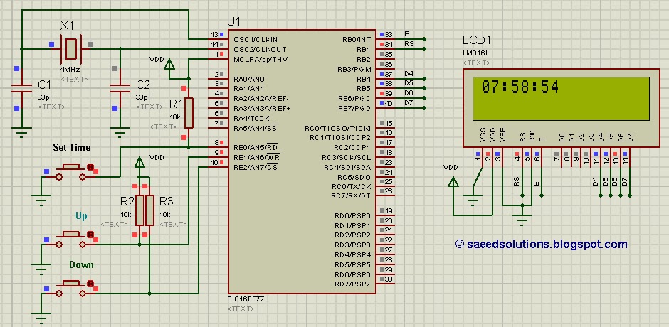
This tutorial on the PIC16F877 microcontroller addresses the question, "How to implement a controllable digital clock using the PIC16F877?" It utilizes the PIC16 simulator for demonstration purposes. The implementation of a controllable digital clock using the PIC16F877 microcontroller involves several...

Many published circuits that flash LEDs require 3 volts or more. This circuit utilizes a single inexpensive C-MOS IC and can flash an LED for an entire year on a single 1.5-volt AA alkaline battery cell. The circuit employs...