
8MHz AM radio transmitter
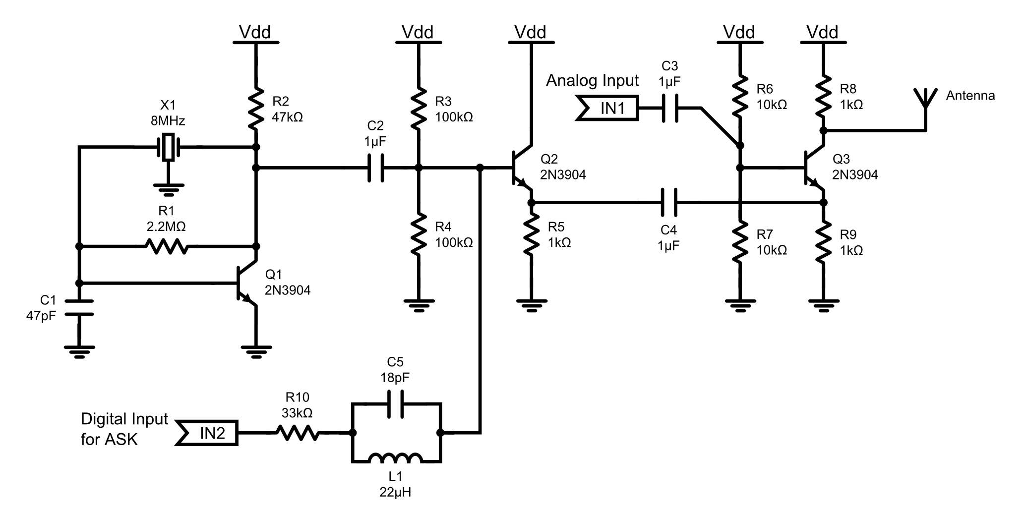
The 8MHz AM radio transmitter operates by modulating the amplitude of a carrier wave at a frequency of 8 MHz. The transmitter circuit typically includes several key components: an oscillator, a modulator, an amplifier, and an antenna.
The oscillator generates a stable 8 MHz signal using a crystal or LC circuit, ensuring that the carrier frequency remains consistent. The modulator combines the audio input signal—often originating from a microphone or audio source—with the carrier wave. This process alters the amplitude of the carrier signal in accordance with the audio input, effectively encoding the sound information onto the radio wave.
The amplified output is then fed to the antenna, which radiates the modulated signal into the surrounding environment. The design may incorporate a low-pass filter to eliminate unwanted harmonics and improve the quality of the transmitted signal.
To ensure proper operation, power supply considerations are essential, typically involving a regulated DC source that provides the necessary voltage and current to the circuit. Additionally, components such as resistors, capacitors, and inductors may be included to stabilize the circuit and optimize performance.
This AM transmitter can be utilized for various applications, such as short-range communication, educational projects, or hobbyist experimentation, making it a versatile tool for electronics enthusiasts. Proper tuning and testing are crucial to achieving the desired transmission range and audio clarity.This is an 8MHz amplitude modulated (AM) radio transmitter, which I built mainly for work, and also as an exercise in electronics (it is the first RF transmitter I`ve ever built). We wanted to have a simple radio transceiver design at our disposal for some possible projects in the future that might require.
🔗 External reference
Related Circuits
Superheterodyne receivers have been mass-produced since around 1924, but for reasons of cost did not become successful until the 1930s. Superheterodyne receivers represent a pivotal advancement in radio technology, characterized by their ability to convert high-frequency signals into lower...
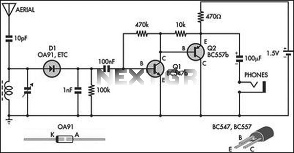
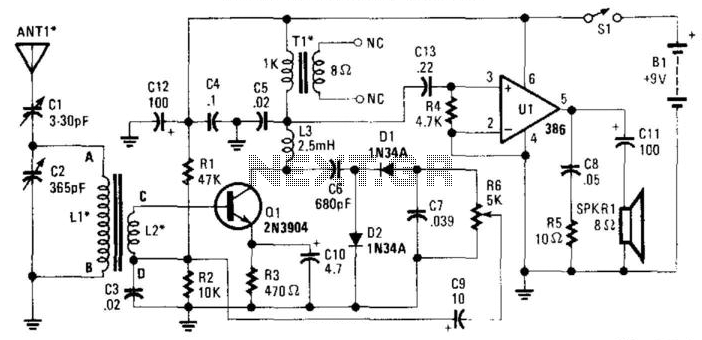
This circuit is an amplified crystal set. The inductor can be a standard AM radio ferrite rod antenna, while the tuning capacitor is a variable plastic dielectric gang designed for small AM radios. The aerial tuned circuit feeds diode...
This small transmitter utilizes a Hartley type oscillator. Typically, the capacitor in the tank circuit would connect at the base of the transistor; however, at VHF frequencies, the base-emitter capacitance of the transistor behaves like a short circuit, effectively...
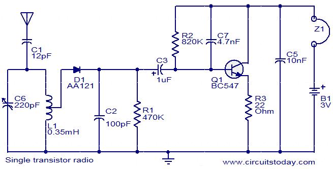
The circuit diagram of a simple radio that uses one transistor and a few other passive components. Component: Diode, Capacitor, Inductor, Resistor. The circuit design for a simple radio receiver typically incorporates a single transistor as the active amplification element,...
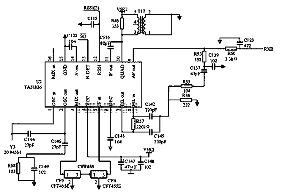
As illustrated in the figure, Vcc is the power supply for the circuit. Upon receiving the initial signal, the frequency is adjusted to 21.7 MHz. This frequency is subsequently enhanced through two crystal filters to improve the selectivity of...
The RF signal is transmitted from the antenna through CI to a tuned circuit consisting of LI and C2. One end of L2 delivers the RF signal to the base of Q1 for amplification, while the other end connects...