
Coin Counter circuit

The circuit for the counter section includes a digital counting mechanism that is capable of recognizing and tallying different coin denominations. The design typically utilizes a microcontroller or a dedicated counter IC to process the signals generated by the coin detection sensors.
For quarters, loonies, and toonies, each coin type is detected by specific sensors that respond to the size and weight of the coins. The sensors generate pulses that are fed into the counting mechanism. The circuit is designed to differentiate between the coins based on these signals.
The counting section may include a display unit, such as a seven-segment display or an LCD, to visually present the total count of the coins. This display is interfaced with the microcontroller, which processes the input from the sensors and updates the display accordingly.
Power supply considerations for the circuit are crucial, as the components must operate reliably under various conditions. A voltage regulator may be included to ensure that the microcontroller and display receive a stable voltage.
In addition, the design may incorporate a reset mechanism to allow for the clearing of the count when needed. This could be implemented with a push-button switch that, when pressed, sends a reset signal to the microcontroller.
Overall, the circuit is designed for efficiency and accuracy in counting coins, making it suitable for applications in vending machines, coin sorting systems, or any automated cash handling systems.The next counter section works the same way but is set up to count 4 quarters, single $1 (loonies) and single $2 (toonies). The toonies circuit is set.. 🔗 External reference
Related Circuits
The circuit consists of an ultrasonic transmitter and a receiver that operate at the same frequency. Ultrasonic piezoelectric transducers serve as the output and input devices, respectively, with their frequency of operation determined by the specific devices used. The...
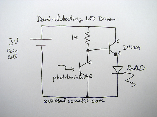
The following circuit illustrates a simple and inexpensive dark-detecting LED circuit. Features include the use of photoresistors, specifically a photocell or LDR, and an LED. This circuit utilizes a light-dependent resistor (LDR) as the primary sensing element. The LDR exhibits...
The BTS412B functions as two high-side power MOSFET switches, while the BU271L components rated for 50V serve as the low-side switches. Together, these elements can form a bi-directional H-bridge DC motor drive circuit, as depicted in Figure 11-1l. This...
This circuit prioritizes a microphone and preamplifier (voice circuit) over any other audio signal, functioning similarly to a one-way intercom. When the push-to-talk switch is activated, the main amplifier switches from music to the voice signal. Essentially, a voice-over...
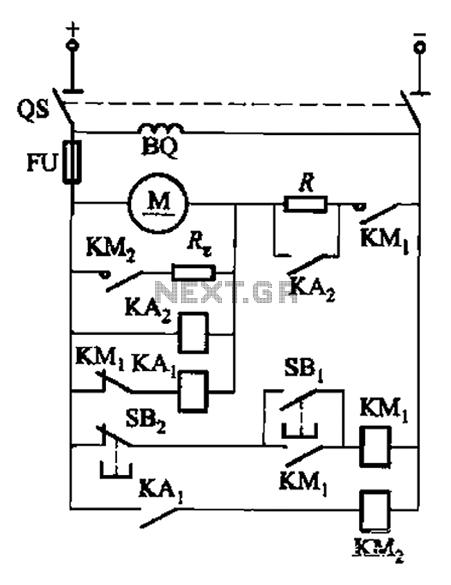
The circuit illustrated in Figure 3-196 features a starting resistance level and an undervoltage relay (KAz) that is controlled by the removal of the startup resistor. It also includes dynamic braking for shutdown purposes. The undervoltage relay (KAL) operates...
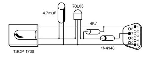
It is unusual that personal computers are not equipped with a standard remote control interface. Many motherboards feature an IRDA port; however, this port is not compatible with the 38 kHz frequencies commonly used by regular remote controls. Fortunately,...