
Arduino Digital audio player
The Auduino project represents an innovative approach to audio playback using an Arduino platform, showcasing the versatility of microcontrollers in handling audio applications. The circuit design incorporates several key components: an Arduino Uno, an SD card reader module, and an audio output stage connected to speakers. The Arduino Uno serves as the core microcontroller, executing the code that manages audio playback and user input.
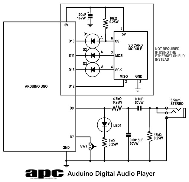
The SD card module connects to the Arduino via the SPI interface, which allows for efficient communication between the two devices. The wiring of the SD card module should be carefully executed, ensuring that the data lines are appropriately connected to the Arduino's digital pins. The inclusion of diodes in the circuit is a critical aspect, as they function as voltage level translators, preventing the 5V logic of the Arduino from damaging the 3.3V SD card module. This is accomplished by using the pull-up resistors present on the SD card module, which help to maintain the correct voltage levels during operation.
The PWM technique is employed to generate an analog signal from the digital audio data stored in WAV files. The Arduino outputs a PWM signal that is filtered to produce a smooth analog voltage. The duty cycle of this PWM signal corresponds to the amplitude of the audio waveform, effectively reproducing the sound when amplified through external speakers. The quality of the audio output is limited by the capabilities of the Arduino, which supports 8-bit audio at a sample rate of 19kHz.
The project also provides an audio converter tool that simplifies the process of preparing audio files for playback. This tool allows users to convert various audio formats into the required WAV format, streamlining the workflow for users who wish to utilize the Auduino player. The converter integrates into the Windows Explorer context menu, making it user-friendly.
In conclusion, the Auduino project exemplifies the potential of Arduino in creating accessible audio playback solutions. By leveraging simple components and techniques, it opens up opportunities for further exploration in digital audio applications, making it an excellent educational project for electronics enthusiasts.So far in this series we`ve had a diverse look at how Arduino can interact with a range of real-world devices from servo motors to ultrasonic range finders TVs to humidity sensors. Now we`ll see if we could get the Arduino to make a few sounds. We`ll actually do a bit better than that we`ll look at the importance of pulse width modulation (PWM ) to microcontrollers by building our own digital audio player called Auduino. A few months ago I stumbled across a simple single-button digital audio player based around a Raspberry Pi developed by a guy for his 90-year-old grandmother who needed something simple to use. All it had was a single button and an LED and it was programmed to play digital audiobooks. The button pressed quickly would pause and play while holding it down for more than four seconds would play the previous track.
I couldn`t help wondering if we could do something similar and simpler with an Arduino. Well you can. We`ve combined an Arduino Uno microcontroller a $1. 50 SD card reader module from eBay computer speakers and some other components to create a simple single-button digital audio player. There`ll be a small amount of soldering involved. Admittedly our player`s WAV file support is modest (mono 8-bit up to 19kHz) but the quality is still more than good enough to handle music and digital audiobooks.
However don`t miss the bigger picture an audio player we can digitally control opens up a world of possibilities. If you`re wondering where you`ll find 19kHz/8-bit/mono WAV files we`ve got that covered. I`ve created an easy-to-use audio converter that integrates into Windows Explorer and converts any audio file into the required WAV format.
You can even convert multiple files at the same time and it automatically turns those files into the 8. 3 filenames our player requires. All you do then is copy the WAV files to the root of a FAT32-formatted Class 4 SDHC card (we`ve tested cards up to 8GB).
Load the card into the player`s SD card reader module press the button and the first track will begin playing. The ability to turn digital data 1s and 0s into a proportional analogue voltage is a fundamental tenement of digital audio and it`s where the digital-to-analogue converter (DAC) gets its most celebrated use.
Audio DACs appear in every smartphone tablet MP3 player PC and laptop. They`re everywhere. DACs are also used to control motors and sensors LEDs and more anywhere where you need to turn a digital number into a real-world analogue voltage. One of the simplest ways to do it is what makes microcontrollers so popular it`s called Pulse Width Modulation (PWM).
The problem for all microcontrollers is that their standard digital outputs only have two positions: high and low. The output will either be at the supply rail (Arduino`s 5V) or ground (0V); there`s no in between. This is where PWM comes in. It starts with a clock signal output that runs at a much higher rate than we need; in our case beyond the 20kHz audio spectrum.
That clock signal is a squarewave meaning it spends half the time at digital-1 and half at digital-0 in each clock cycle. In geek speak we say it has a duty cycle of 50%. What PWM allows us to do is modulate that duty cycle so that when its pulse waveform output is fed and filtered through a particular device the waveform is averaged and becomes an analogue voltage that`s proportional to the duty cycle.
So if the waveform signal varies between 0 and 5V and has a 10% duty cycle it`ll have an average analogue voltage of 0. 5V. At 50% duty cycle it`ll be 2. 5V; at 90% it`ll be 4. 5V. This is how the pulsating LED on your iPhone or iPad works. The LED will be fed with a PWM waveform that varies between 0 and 100% duty cycle at a high enough frequency so you can`t see the LED flashing.
Your typical music file is the result of the reverse process: turning a complex analogue voltage into a digital representation. Audio CDs capture two channels (stereo) at a 44. 1kHz sample rate with 16-bit resolution. What that means is there are 216 or 65536 distinct voltage levels that can be captured every 22. 6 milliseconds or so. It`s called Pulse-Coded Modulation (PCM) and it`s the basic format used by Windows` WAV file format. Look at a WAV file and you`ll see a long series of 16-bit numbers that represents the audio (one per sample and one per channel).
Turning those digital samples back into an analogue voltage is what every audio player does. One way of doing this happens to be PWM. Remember how we said before that a PWM signal is modulated to create a variable duty cycle waveform Guess what we use to modulate the clock signal with The digital audio samples from our WAV file. So what we end up with is a PWM waveform output whose duty cycle is proportional to the PCM audio data in the WAV file.
We feed the output into an audio amplifier and hey presto! We hear that digital audio WAV file coming through the speakers. While we love Arduino this is where we run into its limitations it only has an 8-bit bus and combined with its limited 16MHz clock speed and our audio code library we only have enough speed to handle WAV files with a 19kHz sample rate and 8-bit depth. That said I`ve worked on our simple audio converter to tweak the encoding so it produces good-sounding files with a better than AM radio frequency bandwidth which is good enough for music and certainly more than enough for digital audiobooks.
Download the auduino. zip` file from apcmag. com/arduino. htm and unzip it to the C:Auduino` folder on your C: drive. Launch the InstallWavConverter. reg` file. This installs a Shell registry key that adds a new menu entry to Windows Explorer`s context menu. (Open the REG file in Notepad and you can see how it works. ) Click the Yes` button to confirm and then OK` when it`s completed (RemoveWavConverter. reg` deletes the registry key if you wish). Use Windows Explorer to find an audio file you wish to convert right-click the file and select Convert to APC/Auduino format`. You`ll see a Command Prompt screen appear briefly and when it disappears you`ll have a new WAV file in the original file`s location.
You can even select multiple files to encode all at once. Looking for free downloadable digital audiobooks Try LibriVox and Books Should Be Free. These are usually in MP3 or OGG format with books separated into chapter files. Our encoder can easily turn these into the necessary WAV format. Copy this file(s) to the root folder of a Class 4 FAT32-formatted SD card up to 8GB and transfer the card to the Auduino player. Files can be up to 2GB. Power up the player and press the button. We`re building our prototype this month on the same breadboard we used for our LED dice and weather station projects as it makes it easier to troubleshoot and program the Arduino.
You can see how it goes together from the circuit diagram the overlay diagram and the photos. The SD card module has two rows of pins and each pair is wired together so it can plug straight into the breadboard. If there`s a tricky part of the circuit it`ll be the diodes connecting the Arduino to the SD card module.
It may look like the diodes are facing the wrong way but they`re not. We`ve got a small problem in this project that the diodes are helping to fix for us. Basically the Arduino runs on a 5V logic level (that means the digital outputs swing from 0V to 5V) but SD cards only run on 3. 3V. If we feed 5V into the data lines of the SD card module we risk blowing up the card. The diodes therefore act as a voltage level translator. The SD card module has pull-up resistors on three of the four data lines which lightly connect these lines to the supply rail.
When the Arduino digital output swings low the diodes are forward-biased by the current through the pull-up resistor and the SD module control line drops low to 0. 6V. When the Arduino output rises up to 5V the diode becomes reverse-biased and no current flows from the Arduino to the SD module.
The pull-up resistor lifts the data line to the 3. 3V supply rail so we get our digital-1 at the required 3. 3V instead of the Arduino`s 5V so everyone`s happy. (The SD module has a 3. 3V voltage regulator on board that drives the pull-up resistors. ) Electrical engineers would argue that this is a dodgy fix and we should be using a dedicated level translator chip like a 74HC4050 and they`re right. The diode option does work although as we`ve discovered not reliably. We tested it with half a dozen different SD cards and found two of the six worked well one sort of worked and three didn`t work at all.
Some SD cards expect to see digital signals that snap between 0V and 5V in no more than five nanoseconds while others are more tolerant and they`re the ones that work. The SD card module talks to the Arduino over the SPI (Serial Peripheral Interconnect) bus but SPI is really just a 1-bit economy mode interface that`s easy to implement whereas SD cards normally communicate over a 4-bit wide bus.
Combine our low-level translation circuitry with the fact that not all SD cards do SPI well and that unfortunately limits the cards we can use. We recommend Class 2 or Class 4 SD cards that are preferably 8GB or smaller. You can try larger Class 4 cards (we`ve used a 32GB card successfully) although you`ll need to make some changes to our Arduino code: change the cardType variable from oldCard to newCard.
Basically the newer or larger the card the slower we need to run the SPI bus so doing this drops it back from 8MHz (half-speed) to 4MHz (quarter-speed). Any slower than 4MHz however and the data rate becomes too slow and you can hear the continual jitter in the sound output.
We purchased new 4GB and 8GB Class 4 Verbatim cards. The 4GB card didn`t work but the 8GB card worked perfectly at the 8MHz/half-speed rate. Our modified SD library still works with all existing Arduino programs (sketches) but adds a new instruction that allows us to adjust the Arduino`s SPI speed and allow more cards to work. We`ve also come up with a more reliable option which involves ditching the $1. 50 SD card reader and replacing it with a $10 Ethernet Shield that includes a microSD card slot. You remove the components connected to pins 10 11 12 13 and change the sketch by setting the chipSelect variable to 4 (this is marked in the sketch code).
You also need to set the cardType variable to oldCard. The Ethernet Shield has the proper level translation built in to reliably work with any microSD card. The Shield sits on top of the Arduino and you use the same I/O pins for the switch and audio out. Our Auduino player doesn`t have a built-in amplifier yet so we need external speakers and a way of getting our audio signal to them.
🔗 External reference
Related Circuits
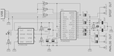
This is a high-quality preamplifier circuit with a built-in USB DAC designed for the Leachamp power amplifier. The schematic is derived from the PCM2902 datasheet. The circuit includes a DAC and ADC, SPDIF output and input, and an HID...
Security is a prime concern in our day-to-day life. Everyone wants to be as much secure as possible. An access control for doors forms a vital link in a security chain. The microcontroller based digital lock for Doors is...
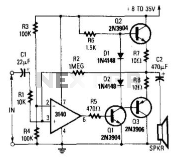
A CA3140 operational amplifier drives a complementary output stage consisting of transistors Q1, Q2, and Q3. The output power is influenced by the supply voltage and the thermal dissipation limits of transistors Q2 and Q3. Under optimal conditions, the...
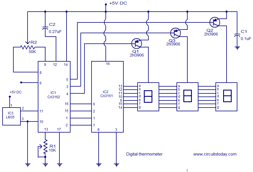
A simple digital thermometer circuit without a microcontroller and featuring a seven-segment LED readout is presented. The circuit utilizes three integrated circuits (ICs): CA3162, CA3161, and LM35. The CA3162 is a monolithic analog-to-digital (A/D) converter with a BCD output....
High-end audio equipment is typically controlled digitally by a microprocessor (microcontroller) system. It is necessary to have a digital interface that allows for effective communication and control. High-end audio systems utilize a microcontroller to manage various functionalities, enabling precise control...
The 2N3819 is an n-channel JFET specifically designed for RF and mixer applications, offering very low noise, minimal distortion, and excellent high-frequency gain. Creating a PCB can be accomplished in a few straightforward steps. Begin by using PCB design...
Warning: include(partials/cookie-banner.php): Failed to open stream: Permission denied in /var/www/html/nextgr/view-circuit.php on line 713
Warning: include(): Failed opening 'partials/cookie-banner.php' for inclusion (include_path='.:/usr/share/php') in /var/www/html/nextgr/view-circuit.php on line 713