
Programmable timer for appliance

The programmable timer circuit is designed to automate the operation of various appliances by allowing users to set specific time intervals for activation and deactivation. This functionality is particularly useful in applications such as lighting control, heating systems, and irrigation systems.
The core of the circuit typically consists of a microcontroller or timer IC, which manages the timing functions. The timer can be adjusted through a user interface, which may include buttons or a rotary switch to select the desired time duration. An LCD or LED display may also be incorporated to visually indicate the selected time and the operational status of the appliance.
The circuit will include a relay or a solid-state switch to control the power supply to the appliance. The relay is activated by the microcontroller when the preset time interval elapses, allowing current to flow to the appliance and turning it on. Once the time expires, the relay is deactivated, cutting off the power supply.
Power supply considerations are crucial for the operation of the timer circuit. A regulated power supply, often derived from an AC to DC converter, ensures that the timer operates reliably without fluctuations that could affect timing accuracy.
Protection features such as diodes may be employed to prevent back EMF from damaging the microcontroller when the relay is switched off. Additionally, capacitors can be used for smoothing and filtering the power supply to ensure stable operation.
The programmable timer circuit can be designed with multiple timing options, allowing for different configurations depending on user needs. This flexibility makes it suitable for a wide range of applications, enhancing the efficiency and convenience of appliance management.Programmable timer for appliance circuit is advanced timer appliance is controlled by timer circuit from 8 sec. to 2 hour.circuit diagram of programmable timer for appliance . 🔗 External reference
Related Circuits
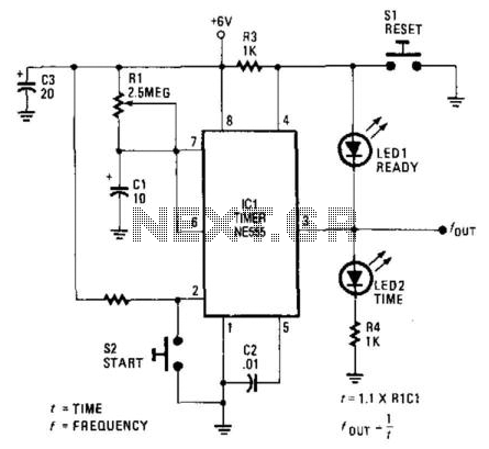
LEDs provide a visual indication of the circuit's status at any moment. Once the reset switch, SI, is activated, the timer maintains that state until the start switch, S2, is pressed. When either switch is engaged, LED1 (indicating "ready")...
The 555 timer is a versatile component that can be utilized as a timer and configured to produce a specific frequency. In Part II of Electronic Project I, a circuit was created to make an LED flash. This time,...
This mini metronome provides a linearly scaled output with a range of 40 to 208 beats per minute. The transistors Q1 and Q2 facilitate the linear frequency variation of IC1. The described mini metronome circuit utilizes an integrated circuit (IC1)...
Telephones are declining globally; however, India has over 350 million mobile phone users, alongside a significant number of traditional telephone users. This telephone timer is designed to save costs by controlling unnecessary time spent during phone calls. This simple...
The two circuits below illustrate the application of the 555 timer to activate a relay for a specified duration by pressing a momentary normally open (N/O) push button. The circuit on the left can be used for longer time...
To achieve a lower parts count than the two-transistor multivibrators, two LEDs can be alternately flashed using a 555 integrated circuit configured as illustrated in Schematic 2. A combination of a 2.2kΩ and a 47kΩ resistor is used to...