
9v stabilized power supply circuit with
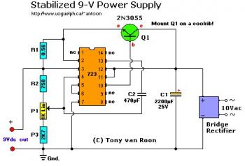
The circuit described functions as a power supply filter, specifically designed to eliminate unwanted noise and voltage spikes from an alternating current (AC) source. The capacitor C1 serves as a crucial component in this filtering process, smoothing out fluctuations in the voltage supply. This is essential for sensitive electronic devices such as a PC mini drill, which can be adversely affected by electrical noise.
The output voltage can be adjusted between 9V and 12V, allowing for compatibility with various devices. This adjustment is achieved through the use of a potentiometer, designated as P1 in the circuit. By varying the resistance of P1, the voltage output can be fine-tuned according to the specific requirements of the connected load.
The circuit may also include additional components such as diodes for rectification, voltage regulators to maintain a stable output, and possibly inductors for further noise suppression. The careful selection of these components ensures that the output remains within the desired voltage range while minimizing ripple and noise to provide a clean and reliable power supply for the PC mini drill or similar devices.
Overall, this circuit exemplifies an effective approach to power supply design, emphasizing the need for voltage stability and noise reduction in electronic applications.C1 filters the noise and spikes off the AC. Adjust the circuit for 9V or 12V output voltage, or whatever voltage level your pc mini drill is using, with the P1 potentiometer. 🔗 External reference
Related Circuits

The simple transistor tester in Figure 1 allows for the identification of the type of transistor and aids in detecting the emitter, collector, and base of the transistor. The simple transistor tester circuit is designed to facilitate the identification of...
The bi-directional sequencer employs a 4-bit binary up/down counter (CD4516) and two "1 of 8 line decoders" (74HC138 or 74HCT138) to create the well-known "Night Rider" display. A Schmitt Trigger oscillator generates the clock signal for the counter, with...
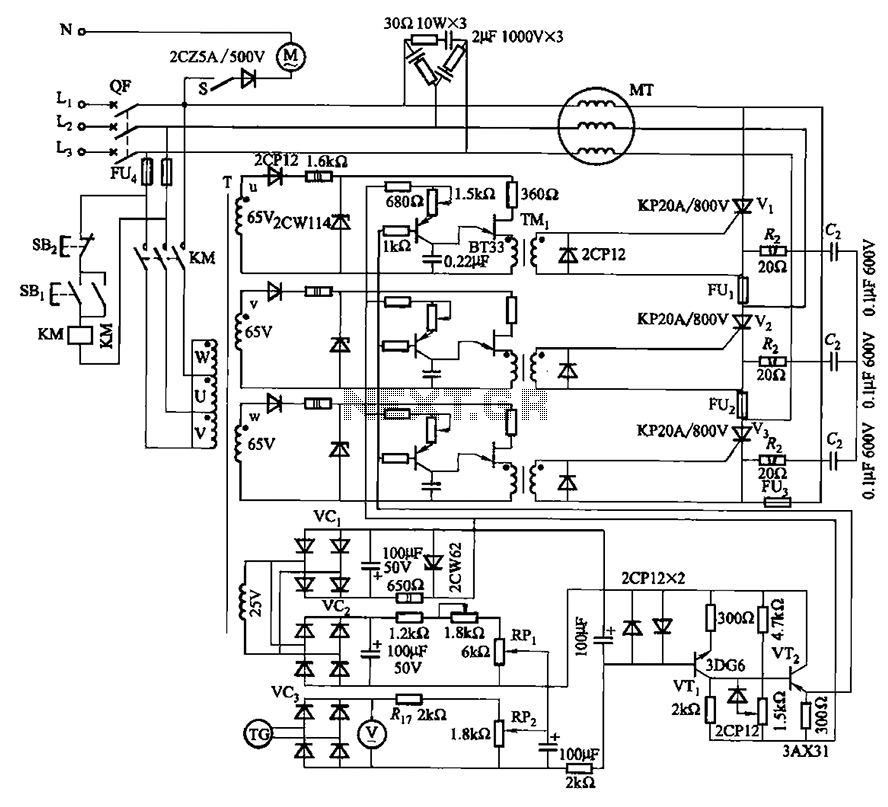
The circuit depicted in Figure 3-181 comprises three thyristors, labeled V1 to V3. The trigger circuit utilizes a single-junction transistor relaxation oscillator. The speed control circuit incorporates negative feedback. A master adjust potentiometer, designated as RPi, is used to...
This circuit is designed to drive a low-power speaker using a sound effects module or a noise generator. It can also be utilized to create amplified speakers for computer use. The circuit amplifies the input signal by a factor...
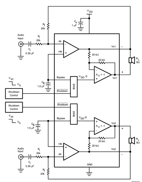
The LM4992 stereo audio power amplifier can be utilized to design a straightforward audio power amplifier project suitable for portable electronic devices. This amplifier circuit is capable of delivering 1 watt of continuous average power per channel to an...
This circuit alerts users when the AC mains supply fails by sounding an alarm and providing a backup light to aid in locating a torch or generator key in the dark. It is powered directly by a 9V PP3/6F22...