
microcontroller driving relay

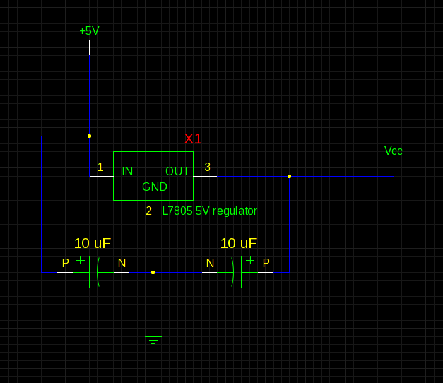
An NPN bipolar transistor is a suitable choice for controlling a relay with a 12V coil, as it allows for isolation between the control circuit and the relay, ensuring that any noise or voltage spikes from the relay do not affect the control circuitry. When designing such a circuit, it is crucial to consider the coil resistance of the relay. For instance, with a coil resistance of approximately 125 ohms, the current drawn can be calculated using Ohm's law (I = V/R). In this case, the relay would require about 96mA (12V / 125Ω), which exceeds the maximum current that a microcontroller pin can safely supply. Therefore, utilizing a transistor to switch the relay is advisable.
The transistor should be connected in such a way that its collector is connected to one terminal of the relay coil, while the other terminal is connected to the positive supply voltage (12V). The emitter of the transistor is connected to ground. The base of the transistor is driven by a microcontroller pin through a current-limiting resistor. The value of this resistor can be calculated based on the desired base current, which should be sufficient to saturate the transistor when the relay is activated.
To ensure reliable operation, a diode must be placed in parallel with the relay coil, oriented to allow current to flow only when the relay is de-energized. This diode serves as a back EMF protection diode, preventing voltage spikes generated by the collapsing magnetic field of the relay coil from damaging the transistor or the microcontroller.
In scenarios where the supply voltage is higher than what the relay coil can handle, a series resistor (e.g., 100 ohms) may be necessary to limit the current through the coil to a safe level. However, this should be calculated carefully to avoid under-driving the relay. The overall schematic should clearly depict these connections, ensuring that all components are rated appropriately for the voltages and currents involved.I usually use an NPN Bipolar transistor to do the relay switching, mainly because my relays are 12v coil rated, but it also keeps everything nice and seperated. and yes i add a diode. with no problem. ( do I or did I need to drive it with a transistor ) but it seam like radio shack is getting out of the parts business.
I`ve got to place a order wit h digikey and though I mite find something better and cheaper. If you know the coil resistance it`s easy to calculate if you need a transistor. If it`s too low (say 125 ©) then you can use two pins to provide 40mA. Make sure you connect between the pins and 5V as the pins can sink more than source. The 100R series resistor is only required if the supply voltage is too high for the coil. The schematic also lacks the all-important back EMF protection diode. 🔗 External reference
Related Circuits
A PIR sensor is triggered when using a timer to wait for 2 seconds after the sensor is activated. Without the timer, the sensor operates as intended. The PIR sensor is connected to an ATMega328p microcontroller, which has three...
The circuit below uses a CMOS dual D flip flop (CD4013) to toggle a relay or other load with a momentary push button. Several push buttons can be wired in parallel to control the relay from multiple locations. More:...
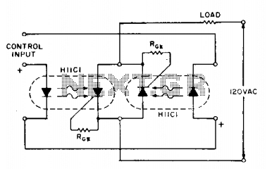
If load current requirements are relatively low (i.e., maximum forward RMS current of 500 mA), an AC solid-state relay can be constructed quite simply by connecting two H11C optically coupled SCRs in a back-to-back configuration as illustrated. The proposed circuit...
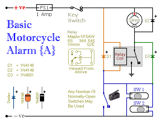
Relays can be utilized to protect motorcycles and have various other applications. When using relays with 6-volt coils, they provide security for "Classic Bikes." The alarms are compact, with completed boards occupying approximately half a cubic inch (8 cc)....
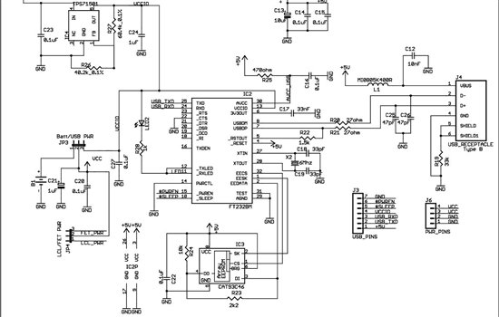
As found in SLAA458, the revised pulse oximeter application, an image of the USB schematic is attached, which is used to output collected data. There are a few questions regarding this schematic: 1) What do J3 and J6 correspond...
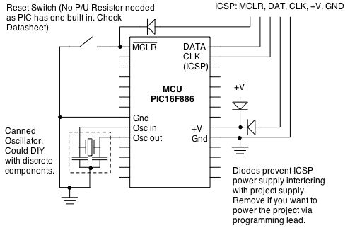
Microcontrollers (MCUs) are versatile integrated circuits that enhance the functionality of electronics, robotics, and other projects. However, they... Microcontrollers (MCUs) serve as the central processing unit in a variety of electronic applications, offering programmable control that allows for complex functionalities...