
A Canon DSLR cable shutter release
A comprehensive electronic schematic for the dual-purpose remote control can be designed based on the outlined requirements. The circuit will include a microcontroller to handle the input from the push buttons as well as to manage the RS232 communication. The microcontroller can be programmed to interpret the button presses for manual operation and to send the appropriate signals to the camera when connected to the Palm PDA for automated control.
The circuit will consist of the following main components:
1. **Microcontroller**: A small microcontroller, such as an ATtiny or PIC, will be used to process the button inputs and manage the RS232 communication. The microcontroller's GPIO pins will be connected to the push buttons and configured to detect button presses.
2. **Push Buttons**: Two tactile push buttons will be used—one for focusing (black button) and one for shutter release (red button). Each button will be connected to the microcontroller with pull-down resistors to ensure stable low states when not pressed.
3. **RS232 Level Shifter**: Since the Palm PDA operates at RS232 levels, a level shifter circuit will be required to convert the microcontroller's logic levels to RS232 voltage levels. This can be achieved using a dedicated RS232 driver IC, such as the MAX232, which converts TTL signals to RS232 voltage levels and vice versa.
4. **Molded Jack Connector**: The circuit will include a 2.5mm jack connector for interfacing with the camera. The jack's tip will connect to the shutter release input of the camera, while the ring may be utilized for additional functions, such as focusing.
5. **Power Supply**: The device will require a power supply, which can be provided by a small battery pack or through a USB connection if the design allows.
6. **Grommet**: For protection against environmental factors, a grommet will be used at the point where the lead enters the plastic enclosure.
The enclosure will be designed to house all components securely, ensuring ease of use and portability. The final assembly will allow for both manual and automated operation, making it a versatile tool for astrophotography. This design approach ensures that the remote control is not only functional but also user-friendly, enhancing the astrophotography experience.The most essential accessory for astrophotography, after a camera, scope and mount, is a remote shutter release to reduce vibration. A remote control is even more useful if it can trigger a series of exposures at preset intervals and of preset duration.
With my Nikon Coolpix 4500 I used a Palm PDA and serial lead with the excellent CoolRemote soft ware. I`ve recently bought a Canon 350d DSLR (this model is also sold under the ghastly name "Digital Rebel xt") and soon found some software called PalmDSLR. However, some electronics is needed to connect the Palm serial port to the camera`s remote control port.
There are several web sites showing how to build an interface. I found those from Cyrille Thieullet (the author of PalmDSLR) and Michael Covington particularly helpful. I decided to make a dual purpose remote control. It has push buttons for manual operation as well as an RS232 socket to connect to a Palm PDA (or other computer) for automated control.
Here is a circuit diagram: I built the adapter in a small plastic box, about 80x50x20mm in size. For neatness I wanted to use a lead with a moulded on 2. 5mm jack plug. I considered buying a suitable ready made audio or video lead and cutting the unwanted plugs off, but found I had a suitable lead already, attached to an unused mobile phone "hands free" set. The lead enters the box through a grommet to give some protection. Here is the remote control connected to camera and PDA. The camera can be focused by pressing the black button, then the shutter can be operated by pressing the red button or by the PalmDSLR program running on the PDA.
Finally, a brief word about choice of Palm model. I had intended to use PalmDSLR with my shiny new Tungsten E2, but soon discovered that this model, and others with the "multi-connector", only has the RS232 data wires (2, 3 & 5) connected and so cannot control the CTS wire. Luckily I still have my old Palm Vx, which does work with PalmDSLR ” leaving my E2 free to control the telescope mount.
🔗 External reference
Related Circuits
The camera has been wired with external shutter leads, and a method is needed to trigger them. These leads must be connected together via a relay at regular intervals, approximately every 2 seconds, starting from launch. A 555 timer...
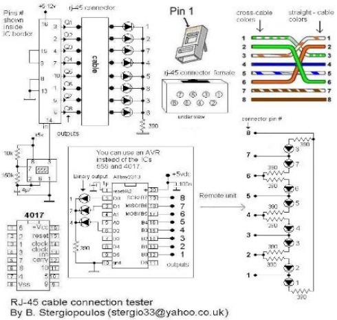
Vasilis Stergiopoulos has developed an RJ45 LAN cable tester. The circuit was initially designed to utilize a 555 timer and a 4017 decade counter IC, but Vasilis has released a schematic and assembly source code for implementing the Attiny2313...
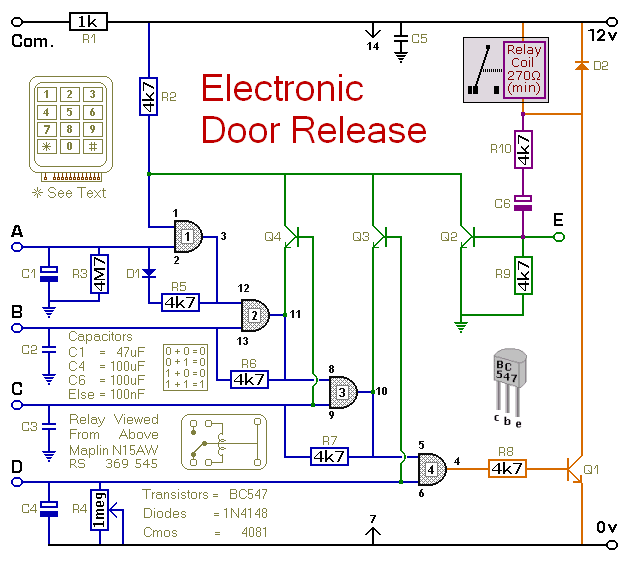
This circuit is designed to operate an electrical door-release mechanism, but it can also be utilized for other applications. When the user enters a four-digit code of their choice, the relay will energize for a preset time period. The...
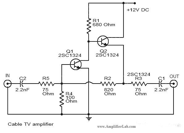
The circuit diagram of a cable TV amplifier has been provided. This cable TV amplifier circuit includes two transistors, Q1 and Q2. The cable TV amplifier circuit is designed to enhance the signal strength of cable television signals, improving the...
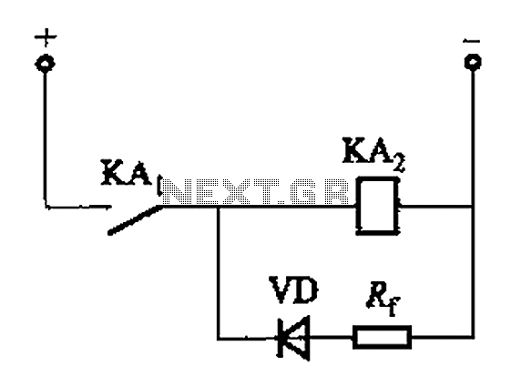
The circuit depicted in Figure 6-24 includes a relay coil with both ends connected in parallel to a resistor (Rf) or an auxiliary diode (VD). This configuration is intended to enhance power after a short circuit occurs in the...
First of all you have to build one cable adapter to connect the female 9pins connector of the modem, with female 9pins connector of the base of E-10G HPC. To build the null modem cable you will need: 2...