
Electronic Door Release circuit
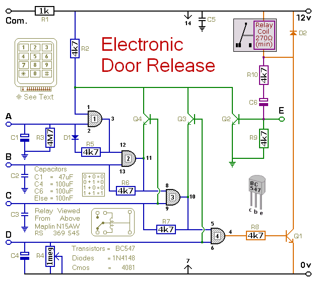
The circuit primarily consists of a microcontroller, a keypad, a relay module, and a power supply. The microcontroller serves as the brain of the system, processing the input from the keypad and controlling the relay based on the entered code. The keypad allows the user to input a four-digit code, which is compared against a stored value in the microcontroller's memory.
When the correct code is entered, the microcontroller sends a signal to the relay module to energize it. This action closes the relay contacts, allowing current to flow to the door-release mechanism, which could be an electronic lock or similar device. The relay is configured to remain energized for a predetermined time, which can be adjusted based on the requirements of the application. After this time period, the relay will deactivate, cutting power to the release mechanism.
The circuit is designed with power efficiency in mind. The standby current is kept to a minimum, allowing the system to be powered by batteries for extended periods without significant drain. This feature makes it suitable for remote installations or situations where access to mains power is limited.
In addition to the primary door-release function, this circuit can be adapted for various applications, such as remote access control for gates, alarm systems, or any device requiring secure electronic access. The versatility of the design allows for easy modifications to accommodate different user requirements, such as changing the code or adjusting the relay timing. Overall, this circuit provides a reliable and efficient solution for electronic access control.This circuit is designed to operate an electrical door-release mechanism - but it will have other applications. When you enter the four-digit code of your choice - the relay will energize for a preset time period.
Use the relay contacts to power the release mechanism. The standby current is virtually zero - so battery power is a realistic option.. 🔗 External reference
Related Circuits
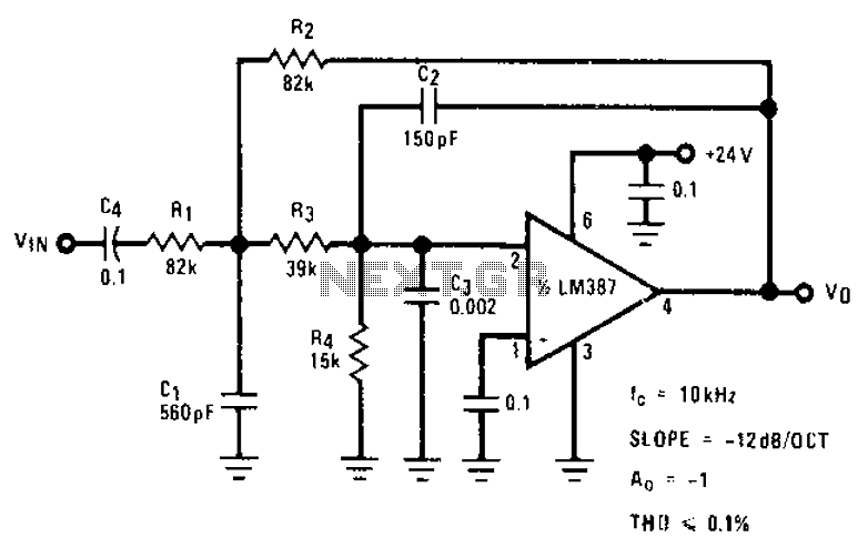
The circuit provides a passband gain of 1 with a corner frequency of 10 kHz, designed to eliminate high-frequency noise such as hiss, ticking, and popping sounds. This circuit operates as a low-pass filter, effectively attenuating frequencies above the specified...
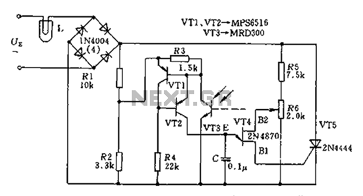
The circuit is designed to stabilize the brightness of lamp L using a thyristor-based AC automatic voltage regulator. The thyristor T5 is connected diagonally across the bridge circuit. The trigger pulses are generated by components VT1, VT2, and VT3,...
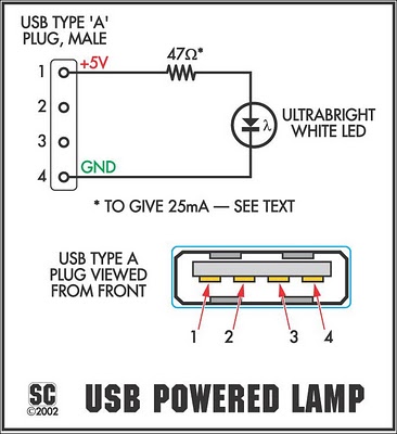
The device is referred to as the Itsy Bitsy USB Lamp. This concept is remarkably straightforward, raising the question of why it had not been conceived earlier. Originating as a student project at Massey University in Wellington, New Zealand,...
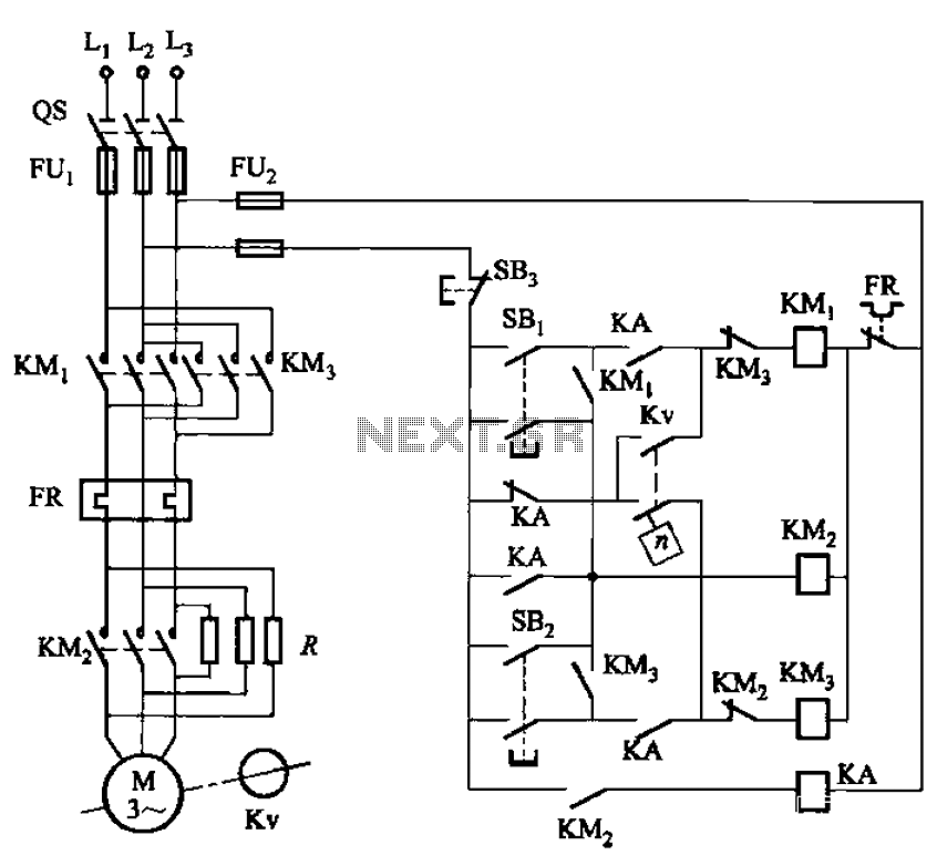
The circuit shown in Figure 3-129 is the C650-2 lathe brake control circuit, utilizing a speed control relay. The C650-2 lathe brake control circuit is designed to manage the braking mechanism of a lathe machine effectively. This circuit incorporates a...
Designed for communications use, this equalizer circuit utilizes a Mitsubishi M5226P audio equalizer IC to modify frequency response. It operates with a supply voltage ranging from 9 to 20 V. Capacitors C6 through C16 are polyester film capacitors with...
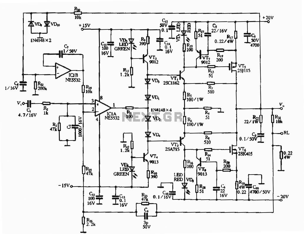
The circuit utilizes an FET amplifier configuration for output, incorporating an NE5532 operational amplifier powered by a 15V supply. The output stage features a FET that amplifies the voltage after passing through several stages. The bias circuit for the...