
A contact-less digital tachometer based on optical sensors

The overall theory of how the circuit and microcontroller function to create an RPM counter involves an IR circuit that outputs pulses whenever it is interrupted, commonly referred to as a photo-interruptor circuit. The PIC microcontroller remains in standby mode, waiting for the rising edge of one of these pulses. Upon detection of a rising edge, the PIC interrupts the current software execution and runs a specific subroutine to register the signal change. By tracking the frequency of these changes using a timer, instantaneous RPMs can be estimated, resulting in a digital tachometer. The output signal from the photo-interruptor circuit will produce +5V pulses whose duration is dictated by the time the emitter and detector are interrupted. By calculating the period of time between photo-interrupts, the current RPMs of the system can be estimated. The formula incorporates the current frequency of the system, with a 4 MHz oscillator being used. Since the PIC requires 4 clock cycles to execute one instruction, this value is multiplied by 4. Additionally, the period between photo-interrupts is multiplied by 7, corresponding to the 7 blades of the fan, allowing for the calculation of one full rotation of the fan.
The circuit is designed to provide a reliable and accurate measurement of rotational speed, making it suitable for various applications in automotive, industrial, and hobbyist settings. The integration of the PIC microcontroller enables flexibility and programmability, allowing for potential enhancements such as data logging or integration with other systems. The 16x2 LCD display provides a clear and user-friendly interface for real-time RPM readings, making it an effective tool for monitoring and analysis. Proper attention to wiring and component selection will ensure optimal performance and longevity of the digital tachometer circuit.The circuit for the Digital Tachometer/RPM Counter consists of only a few devices. Wire them up according to the following circuit diagram. The PIC I`m using is on a demonstration board, which means the clock, power and ground pins are already wired up so I didn`t bother to include that on the schematic. This is the digital tachometer portion of circuit that will send +5v pulses to the RC2/CCP1 pin of the pic. The CCP module, specifically the capture module #1 on the PIC is located at this pin. This is the standard 16x2 character LCD and the interface consists of 8 bits of data, with 3 control signals. Power, Ground and Contrast are the last signals to wire up. The PIC sends commands to this 16x2 LCD over the control and data lines and the LCD does what it is told.
The HD44780 system that this LCD uses is standarized and the datasheet is widely available. First, let me explain the overall theory of how the circuit and microcontroller will work to achieve our goal of building an rpm counter. The IR circuit will output pulses whenever it is interrupted (this type of IR circuit is also known as a `photo-interruptor` circuit).
The PIC microcontroller will stand by waiting to see the rising edge of one of these pulses. Anytime a rising edge is detected the PIC will interrupt the current software and run a special subroutine to take note that the change on the signal occured. Now, if we keep track of how often that change occurs using a timer, we can estimate the instantaneous RPMs, making a digital tachomter!
The actual output signal from the photo-interruptor portion of the circuit will look similar to what you see above. The length of the +5 pulses are determined by how long the emitter and detector are interrupted. If we know the period of time between photo-interrupts using the theory above, we can now estimate the current RPMs of the system.
The forumla above, shows how. The Fosc is the current frequency of your system. I used a 4 MHz oscillator. Since the PIC takes 4 clock cycles to execute 1 instruction, we have to multiply it by 4. On the bottom, the reason we multiply the period between photo-interrupts by 7 is because the fan I`m using has 7 blades. Period*7 = 1 full rotation of the fan. 🔗 External reference
Related Circuits
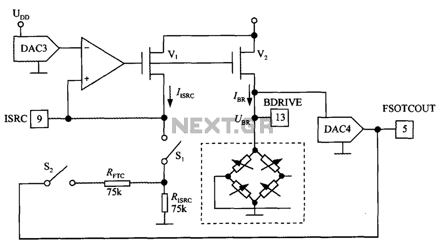
The excitation circuit for the digital pressure signal conditioner MAX1458 is illustrated. The output DAC3 is utilized to adjust the sensor excitation current (IBR), enabling full-scale fine calibration. The reference current (IISRC) is determined by the resistor RISRC and...
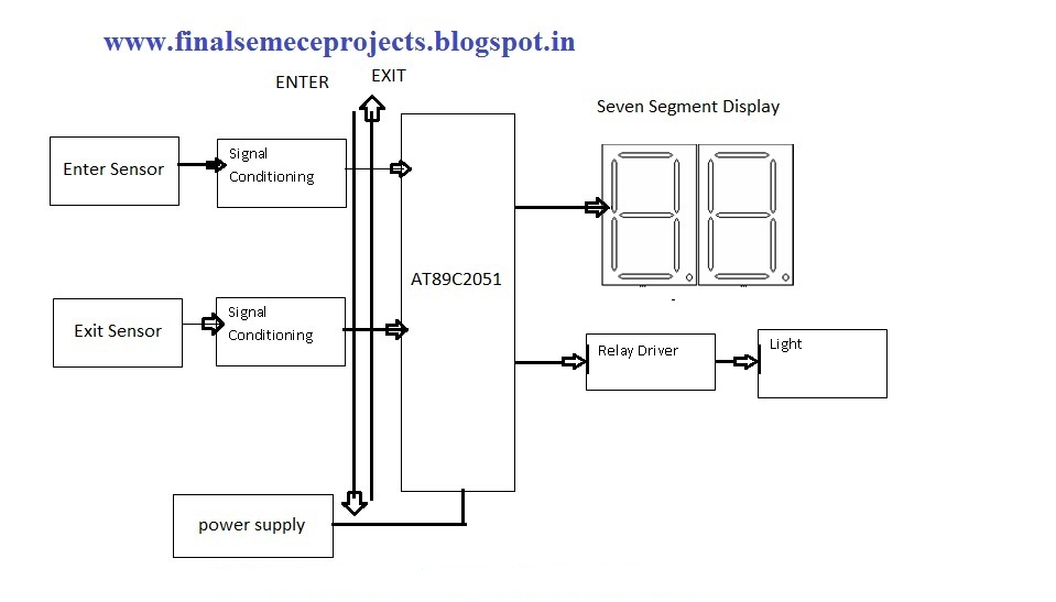
This project involves an automatic room light controller with a bidirectional visitor counter using a microcontroller. It is designed to manage room lighting and accurately count the number of individuals present. When a person enters the room, the counter...

The circuit described is a crystal oscillation circuit using a CM OS inverting configuration, designed to ensure accurate operation. It employs a BCD counter (IC2) capable of achieving a maximum oscillation frequency of 2 MHz, which is 100 times...
The WWVB signal is transmitted as a 60 kHz carrier wave that is amplitude modulated with a time code frame updated once every minute. The data rate is one bit per second. The data frame includes synchronization bits, calendar...
This electronic clock comprises the LM8365 and the LDD640R displays. The LM8365 can show the hour/minute and month/day. Users can set two alarm outputs, AD1 and AD2, by pressing either the 12h or 24h button. The operating voltage range...
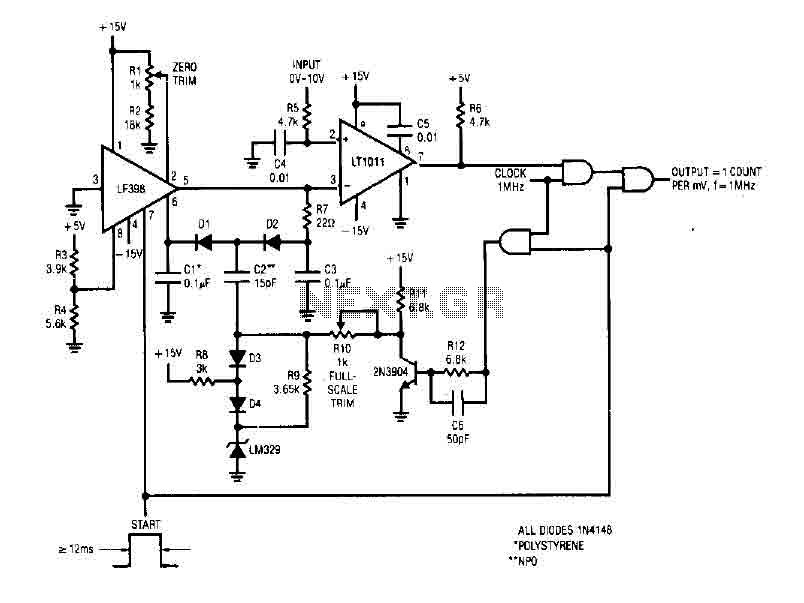
The simple 4-digit converter circuit has an output count of 1, designed for a frequency range from f-IMHz to 10.000 MHz. All diodes used in the circuit are IN4146 "POLYSTYRENE" NPO. The circuit utilizes the LF398 at the input...