
Colpitts oscillator using transistor. Circuit diagram and theory
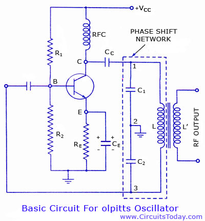
The Colpitts oscillator is a type of electronic oscillator that generates sine waves and is widely used in various applications such as radio frequency generation and signal processing. It utilizes a combination of capacitors and an inductor to create a feedback loop, enabling the generation of oscillations. The basic configuration includes a transistor or operational amplifier (op-amp) as the active component, which amplifies the signal, and a tank circuit composed of capacitors and an inductor that determines the oscillation frequency.
The frequency of oscillation in a Colpitts oscillator can be derived from the formula:
\[ f = \frac{1}{2\pi \sqrt{L \cdot C_{eq}}} \]
where \( L \) is the inductance, and \( C_{eq} \) is the equivalent capacitance of the two capacitors in series, given by:
\[ C_{eq} = \frac{C_1 \cdot C_2}{C_1 + C_2} \]
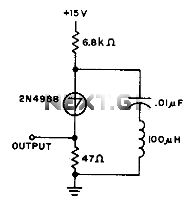
In the transistor configuration, the Colpitts oscillator typically employs a common-emitter amplifier circuit. The capacitors are connected in a voltage divider configuration, providing the necessary feedback for oscillation. The op-amp variant, on the other hand, utilizes the feedback capabilities of the op-amp to maintain the oscillation, where the capacitors and inductor still play a critical role in determining the frequency.
The design of a Colpitts oscillator requires careful selection of the components to achieve the desired frequency stability and amplitude. Additionally, considerations regarding the power supply and biasing of the active device are essential to ensure reliable operation. The simplicity and effectiveness of the Colpitts oscillator make it a popular choice for generating precise frequency signals in various electronic applications.Colpitts oscillator circuit diagram and theory. Colpitts oscillator frequency equation. Colpitts oscillator using transistor. Colpitts oscillator using opamp.. 🔗 External reference
Related Circuits
The capacitor charges until the switching voltage is reached. When the switch (SUS) is activated, the inductor causes the current to oscillate. When the current through the switch drops below the holding current, the device turns off, and the...
This article describes a 2-Input alarm developed on the PIC LICK-1 Module using a Microchip PIC16F628-04. The program uses the internal 4MHz oscillator and if any other frequency is used, the timer values will need to be changed. A...
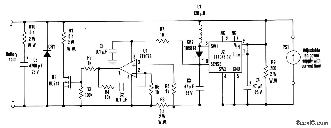
When developing a battery charger, using a real battery can be impractical. The battery simulator circuit described here serves as an alternative. The positive and negative terminals of the battery input should be connected in place of the actual...
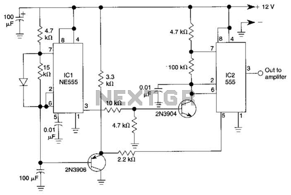
This circuit utilizes two 555 timers to generate a low-frequency tone that gradually increases to a high-frequency tone over the course of approximately 1 second. Following this, the sound ceases for about 0.3 seconds before the cycle begins anew....

This circuit design generates a stable 1 kHz sine wave using an inverted Wien bridge configuration with components C1-R3 and C2-R4. It offers a variable output, low distortion, and low output impedance to ensure good overload capability. The circuit...
A tone generator operates on as little as 1.5 VDC using the Sallen-Key configuration. The tone generator will be applied to implement a phantom-powered signal source for testing balanced microphone inputs. Textbooks and web pages typically depict the Wien...
Warning: include(partials/cookie-banner.php): Failed to open stream: Permission denied in /var/www/html/nextgr/view-circuit.php on line 713
Warning: include(): Failed opening 'partials/cookie-banner.php' for inclusion (include_path='.:/usr/share/php') in /var/www/html/nextgr/view-circuit.php on line 713