
A Dozen Small Battery-Powered Alarm Projects
The described alarm circuits are designed for versatility and efficiency, particularly in battery-powered applications. The low standby current ensures minimal power consumption, extending battery life, which is critical in portable or remote applications. The flexibility in switch selection allows for customization based on user preferences or specific installation environments. The use of a piezo buzzer as the output device is advantageous due to its low power requirements and effective sound output, making it suitable for various alarm functions.
In applications where a relay is preferred, it is crucial to select a relay that operates within the specified current limits to prevent damage to the driving transistor. The ability to switch larger loads via the relay opens opportunities for integrating these circuits into home automation systems, security systems, or other electronic projects requiring alert mechanisms.
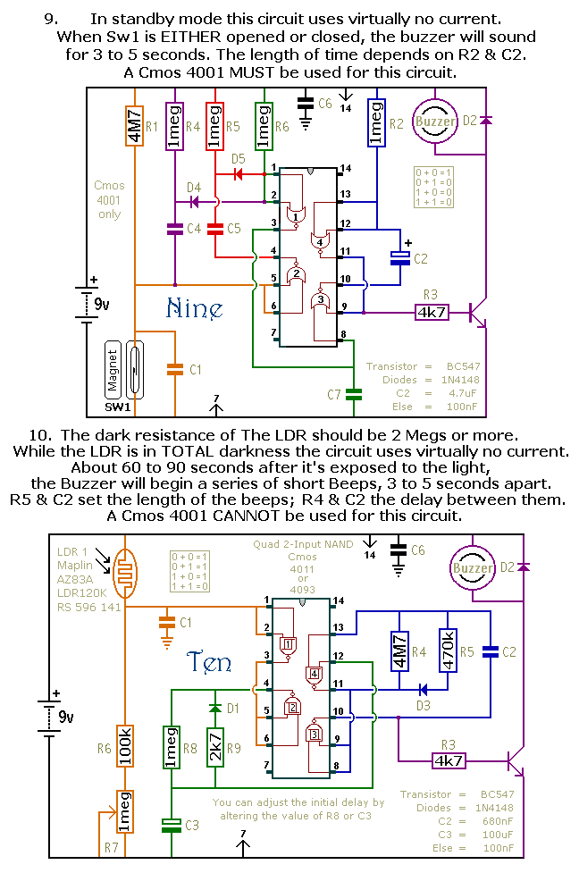
The choice of the CMOS 4093 over the 4011 enhances the circuit's responsiveness and reliability, particularly in time-sensitive applications. The Schmitt-Trigger configuration provides hysteresis, which helps prevent false triggering due to noise or fluctuations in the input signal. This feature is especially beneficial in environments where electrical interference may be present.
The temperature-sensitive circuits, identified as circuits 11 and 12, utilize a thermistor for temperature detection, enabling the design of temperature alarms or triggers. The adjustable resistor values (R6 and R7) allow for fine-tuning the temperature thresholds and sensitivity, making these circuits adaptable for various thermal monitoring applications, such as temperature alarms in HVAC systems or environmental monitoring devices.
Overall, these alarm circuits represent a robust solution for a wide range of applications, combining low power consumption with flexibility and adaptability to specific user needs. The detailed characteristics of the components and their configurations allow for extensive customization while maintaining reliable operation.This is a selection of small self-contained alarm circuits. The main features of each alarm are described on the circuit diagram itself. They all have a very low standby current. So they are ideal for battery operation. Each pair of circuits will print out on an A4 sheet. Although they are described as alarm circuits - they will have other applica tions. Sw1 is drawn as either a micro-switch or a magnetic-reed contact but - so long as it does the job - you can use whatever type of switch you like. Use more than one switch if it suits your application. The output device is a "piezo" buzzer - requiring a current of about 10mA. But - you can replace it with a relay - and use the relay contacts to switch whatever device you like.
Just make sure that the relay coil doesn`t draw more than about 50mA - otherwise the transistor might be overloaded. The Cmos 4093 is the Schmidt-Trigger version of the Cmos 4011. For present purposes the two are interchangeable. However, the 4093 has an improved switching performance. It`s most noticeable when the time periods are extended substantially. The precise length of any time period will depend on the characteristics of the actual components you`ve used - especially the tolerance of the capacitors - and the exact switching voltages of the Cmos Gates.
In the case of circuits 11 & 12 - treat the values of R6 & R7 as a rough guide. The switching point of Gate 3 and the characteristics of the thermistor will determine the actual temperature range available. Changing the value of R6 will allow you to access different areas of the temperature scale - while changing the value of R7 will allow you to alter the width of adjustment available.
🔗 External reference
Related Circuits
This device is notably loud despite operating on only two AA batteries. It employs a push-pull transformer output. The unit was produced with a 10K resistor connected to pin 4 instead of pin 3 due to an error in...

This circuit emits a beep and/or illuminates an LED when someone touches the door handle from outside. The alarm will sound until the circuit is switched off. The described circuit functions as a touch-sensitive alarm system designed to enhance security...
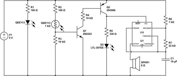
The function of this circuit is to detect a sudden shadow falling on the light sensor and to activate a buzzer when this occurs. The light sensor is designed to monitor ambient light levels. The circuit utilizes a light-dependent resistor...
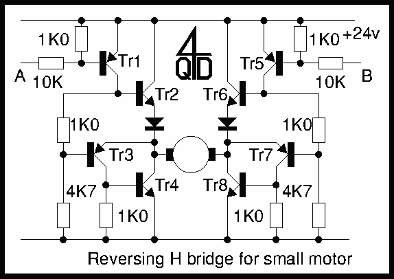
Two inputs, A and B, control the bridge. With both high (or open circuit) both ends of the motor are connected to 0v. Connect A low and Tr2 turns on causing the motor to go forward. Connect B low...
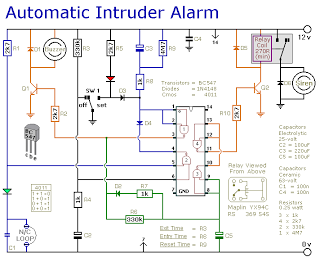
This is a simple single-zone burglar alarm circuit. Its features include automatic exit and entry delays and a timed bell/siren cut-off. It is designed to be used with the usual types of normally-closed input devices such as magnetic reed...
This circuit detects when a tube is empty and pulses a piezo buzzer at 5-second intervals. It is currently operational with a 5V supply on a breadboard but needs to be adapted for a 12V supply from a wall...
Warning: include(partials/cookie-banner.php): Failed to open stream: Permission denied in /var/www/html/nextgr/view-circuit.php on line 713
Warning: include(): Failed opening 'partials/cookie-banner.php' for inclusion (include_path='.:/usr/share/php') in /var/www/html/nextgr/view-circuit.php on line 713