
Three single junction transistor time relay circuits
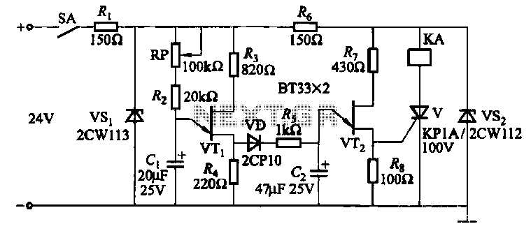
The three single-junction transistor time relay circuits are designed to provide a reliable timing function through a combination of exponential and pulse charging methods. The first stage of the circuit employs unijunction transistors (UJTs), which are known for their ability to generate precise timing signals due to their unique characteristics in switching and controlling current flow. In this configuration, capacitor C1 is charged exponentially, which allows for a gradual increase in voltage until a predetermined threshold is reached, triggering the next stage of the circuit.
The second stage, utilizing a different unijunction transistor (VT2), is responsible for a more abrupt change in voltage across capacitor C2. This stage's pulse charging approach ensures that once the capacitor reaches a certain voltage level, it can rapidly discharge, providing a quick response suitable for applications requiring immediate action after a delay. The combination of these two stages effectively creates a two-stage relaxation oscillator, where the total delay time is determined by the product of the individual delay times from each stage.
In practical applications, this circuit can be used in various timing and control systems, such as in industrial automation, where precise timing is essential. The ability to achieve long delay times makes it suitable for processes that require significant waiting periods before activation. The circuit's design ensures stability and reliability, making it an excellent choice for time delay relays in electronic systems.Three single-junction transistor time relay circuits It uses pulse charging circuit, and therefore can be done for a long time delay, maximum up to tens of minutes. FIG unijunctions VTi and other groups into the first stage delay circuit, charging the capacitor Cl way exponential change; VTz other components of the second stage delay circuit capacitor Cz charging method for the pulse charging, the terminal voltage step change. The total time of the circuit, the equivalent of a two-stage relaxation oscillator delay time of the product.
Related Circuits
Power line fluctuations and cut-offs can damage electrical appliances connected to the line, particularly domestic appliances like refrigerators and air conditioners. When a refrigerator operates on low voltage, excessive current flows through the motor, leading to overheating and potential...
This article discusses the utilization of old PCs as simple controllers. Many obsolete systems, such as the 8088, 8086, 80286, 80386, and 80486, are no longer capable of running modern software, yet they can still function effectively. Often, individuals...
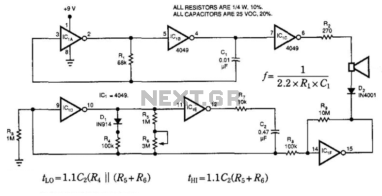
This circuit utilizes a single integrated circuit (IC) to generate a pleasant tone and features one control for adjusting the tone's chiming rate. The circuit comprises several components: IC1A and IC1B, which function as an astable multivibrator, producing the...
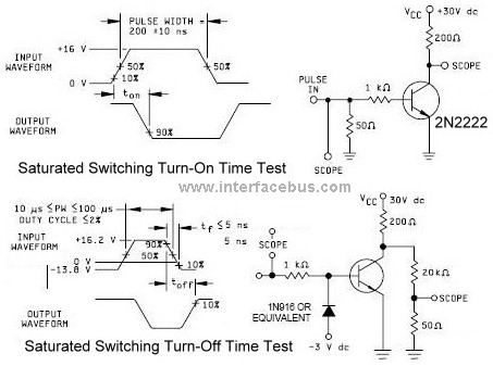
The first circuit tests the saturated turn-on time, while the second circuit tests the saturated turn-off time for a 2N2222 transistor. The first circuit schematic takes the output from the collector, which is pulled high to Vcc, while the...
A new user has joined the forum and is seeking assistance with circuit design. They express a desire for guidance and acknowledge their inexperience in the subject. In circuit design, it is crucial to understand the fundamental components and their...
This page shows three circuits for using the 555 timer IC as a photocell controlled train detector. The circuit is shown driving light emitting diodes but any load of less than 200 milliamps could be used. Shown on the...