
RF Probe Circuit
The RF probe circuit typically consists of a diode, a resistor, and a capacitor arranged in a configuration that allows for efficient signal detection and conversion. The diode serves as the primary component for rectifying the incoming RF signal. When the RF signal is applied to the circuit, the diode conducts during the positive half-cycle, allowing current to flow through the load resistor. The resulting voltage across the resistor is proportional to the RF signal's amplitude.
To enhance the circuit's performance, especially at higher frequencies, a bypass capacitor is often included in parallel with the load resistor. This capacitor helps to stabilize the DC voltage output by filtering out any high-frequency noise that could affect the measurement accuracy. Additionally, the choice of components, such as the diode type and the resistor value, is crucial for optimizing the probe's response across the desired frequency range.
For practical applications, the RF probe can be connected to an oscilloscope or a voltmeter to visualize or quantify the rectified signal. Calibration of the probe may be necessary to ensure accurate voltage readings, particularly when measuring signals at the upper end of the specified frequency range. It is also essential to maintain proper grounding techniques to minimize interference and ensure reliable measurements.
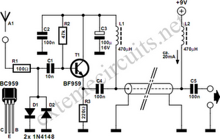
In summary, the RF probe circuit is a valuable tool for engineers and technicians working with RF equipment, providing a straightforward method for measuring RF voltages across a wide frequency spectrum while emphasizing the importance of component selection and proper usage to maintain measurement integrity.A RF probe is a circuit for testing equipment that converts a high frequency signal into a DC voltage. In this way it is very easy to measure RF voltages for either testing or adjustments of transmitters, receivers, modulators.
The RF probe circuit described here is suitable for signals with the frequency range from about 100 kHz to 1000 MHz. Alth ough the diode used here can, in principle, go up to 3 GHz, the impedance of the ground connection will adversely influence the measurement at very high frequencies. Also, please keep in mind to use this probe only on low RF power. 🔗 External reference
Related Circuits
Colour sensor is an interesting project for hobbyists. The circuit can sense eight colours, i.e. blue, green and red (primary colours); magenta, yellow and cyan (secondary colours); and black and white. The circuit is based on the fundamentals of...
This simple circuit is started running by connecting a twelve volt battery across the terminals, causing the large diameter Light-Emitting Diode to light up. When the battery is removed, the LED stays lit up because the circuit has become...

A circuit is needed to drive three or more LEDs at a current of 200-350mA each, with the capability to randomly flash or strobe them at a frequency of 5-20Hz. The input power should be low-voltage DC, with a...
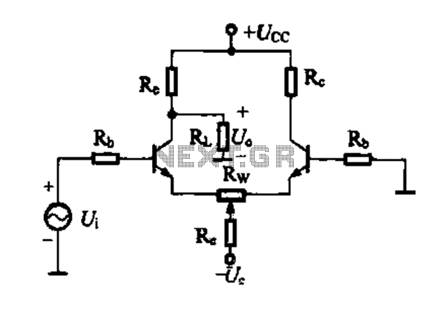
A differential amplifier circuit can be connected in four different ways, allowing for a comparison of their characteristics. The gain of the amplifier is equivalent to that of a single tube, with half the gain providing a high common-mode...
Function: step down the antenna impedance from high to 50 ohms and not, as would be expected, to effect a change from balanced to unbalanced. Component: .. In the context of antenna systems, impedance matching is crucial for maximizing power...
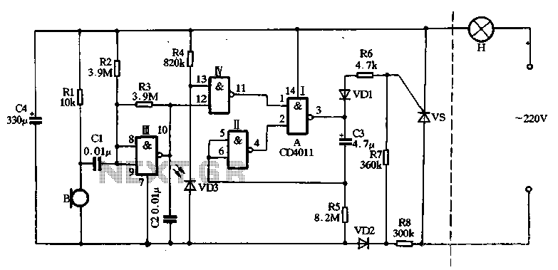
The main circuit utilizes a two-input NAND gate composed of four digital integrated circuits. This includes a NAND gate microphone amplifier circuit, a light control mechanism using an "AND gate," and a monostable delay control circuit formed by NAND...