
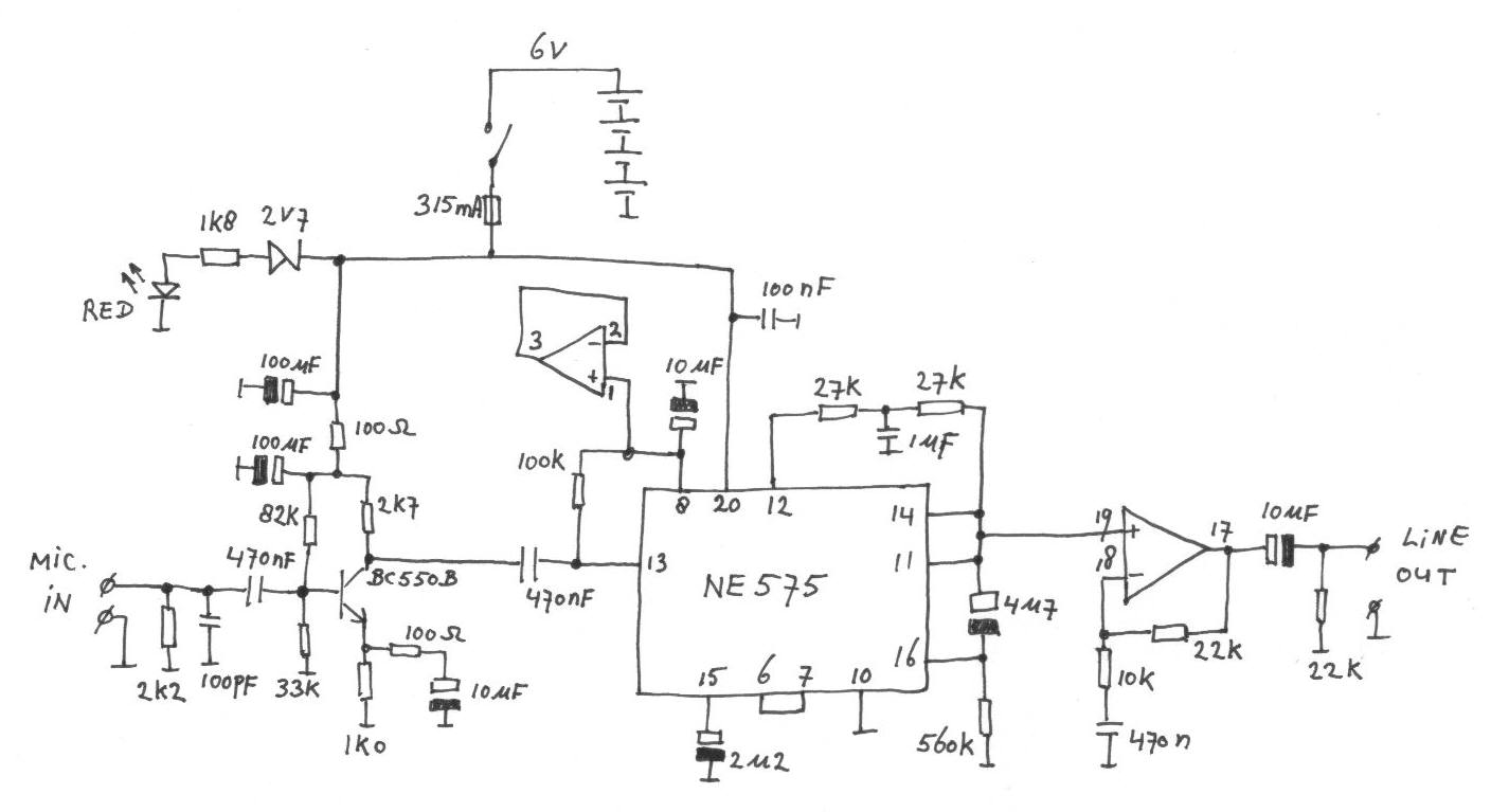
A poormans oscilloscope
The µSCOPE architecture leverages the capabilities of the 12F675 microcontroller, which is adept at processing analog signals and performing digital signal processing tasks. The ADC's sample and hold feature ensures accurate representation of the input signal by briefly holding the sampled voltage for conversion. The comparator's role in triggering enhances the usability of the oscilloscope by allowing users to capture specific events in the input signal, making it suitable for various applications in electronics experimentation. The design's modular nature permits users to modify or expand the input circuitry, accommodating different signal types or levels, thus providing flexibility for diverse electronic projects. Overall, the µSCOPE represents an innovative approach to oscilloscope design, utilizing modern microcontroller technology to create an accessible and functional measurement tool for hobbyists and engineers alike.The oscilloscope is still one of the most important measurement tools of the electronic engineer. With the advent of the often very reasonably priced USB scopes, such an instrument is now within reach of every body. Twenty five years ago that was quite a different story. A (good) oscilloscope was then a very expensive instrument available only to a happy few. As a result many electronics hobbyist made their own scope. The popular electronics magazines in the sixties and seventies were full of scope designs almost always based on vacuum tubes. This period was closed in 1975 when the Dutch electronics magazine Elektuur (in the rest of the world known as Elektor) published their fully transistorised "Elektorscoop".
Despite all this, the purchase of the expensive cathode ray tube and Special high voltage transformer remained too expensive for many people. In an effort to lower the price for a scope even further, Elektuur published in 1978 the "Videoscope".
The Videoscope sampled the analog input signal and stored the samples in a bucket brigade (CCD) memory. Next the data in the CCD was converted into an ordinary (black and white) video signal which could be displayed on an ordinary TV.
In order to view the signal in the normal way the TV had to be put on his side, but nobody minded that. All in all it was still a rather complex design comprising a few dozen of ICs and several printed circuit boards.
These days this obviously can be done much simpler. The present generation of micro controllers is so powerful that such a videoscope concept can be realized almost completely in software. Recently I obtained a sample of the 12f675. On examination of the datasheet of this small 8 pins micro controller from Microchip, it appeared that the small package contained all the components of a miniature videoscope.
In short the µSCOPE project was born, with as main objective the challenge of implementing such a relatively complex task in this small micro controller. The result summarized on this web page is a fully functional (memory)scope that samples the analogue input signal and subsequently displays it on a normal TV (Fig.
1). Unfortunately the µSCOPE works only on 625 line PAL standard TVs, sorry. It was never the intention to build a sophisticated measurement instrument. Nevertheless, signals up to a few kHz are reasonably well displayed by this simple circuit that can be build for only a few euro. Hopefully this "poor mans" scope may be of good service to especially the young electronics hobbyist.
The 12f675 is one of the smallest members of the Microchip micro controller family. In the 8 pin package we find a 14-bit processor core, 1k word FLASH program memory, 64 bytes RAM and 128 bytes data EEPROM. Next to the standard peripherals such as two timers, a watchdog timer etc. the 12f675 is also equipped with a 10-bit AD converter with sample and hold, a comparator and a programmable voltage reference.
Al these components can be configured under software control and Fig. 2 depicts how this is done for the µSCOPE. Pin 6 is used as the analogue input. Internally this pin is connected via the sample and hold to the AD converter. Since the supply voltage is used as the reference voltage for the AD converter, the measurement range is exactly from 0 to 5V. Pin 6 is also connected to one of the inputs of the comparator to implement the trigger function of the µSCOPE.
The trigger level is determined by the programmable voltage reference which is connected to the other input of the comparator. Since it is possible to invert the output of the comparator by software, it is possible to trigger on a positive or negative slope.
The input circuit of the µSCOPE is kept as simple as possible and can be expanded depending on individual wishes. The input signal is first DC decoupled by C6. R8 and R9 set the "zero level" at half the supply voltage. The first line of protection against too high i 🔗 External reference
Related Circuits
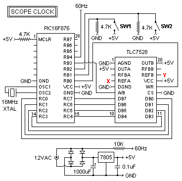
This oscilloscope clock project utilizes a PIC 16F876 microcontroller and a digital-to-analog converter (DAC) to generate X and Y signals for displaying a clock on an oscilloscope. The original circuit and software were designed by OZ2CPU. The clock circuit...
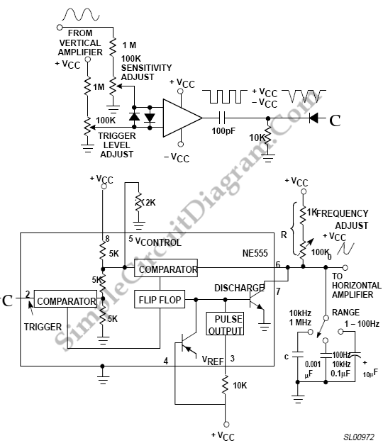
The 555 timer can be utilized to reduce the cost of incorporating a triggered sweep into an economical oscilloscope. The timer is activated by the input operational amplifier of the circuit. The application of the 555 timer in an oscilloscope...
There are several Instructables and other internet-based instructions on how to modify a television set into an audio visualizer or other simple applications. To transform a television set into an audio visualizer, a detailed understanding of both the television's hardware...
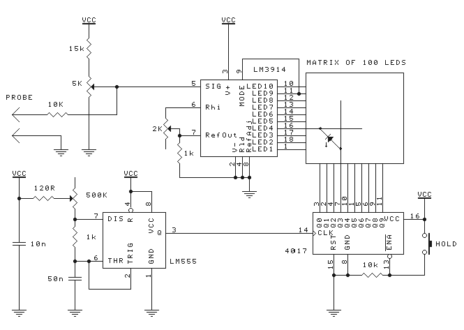
Probably the best advantage is its very small size and the fact that it can run off the power supply of the circuit being tested. Although it has a low frequency range, it can still be used for most...
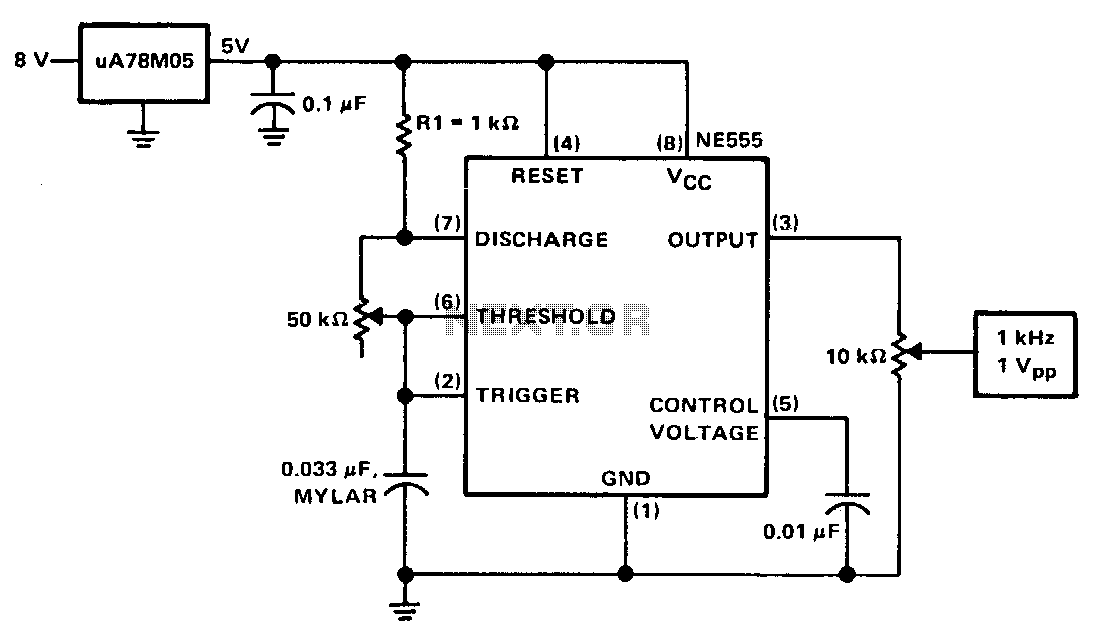
The calibrator can be utilized to verify the accuracy of a time-base generator and to calibrate the input level of amplifiers. It consists of an NE555 timer configured in astable mode. The oscillator frequency is precisely set to 1...
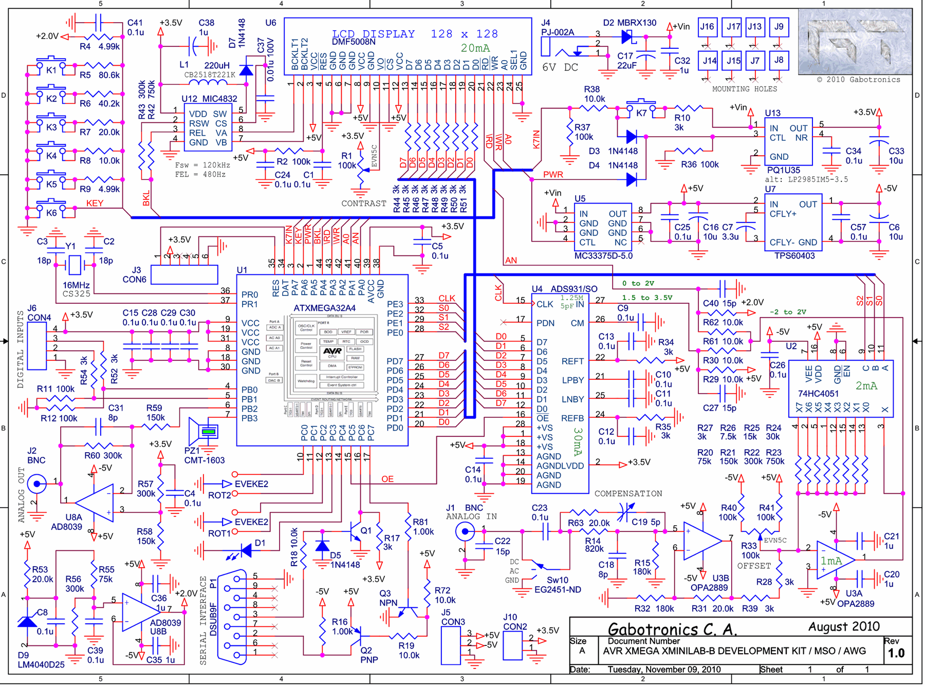
The Xminilab-B oscilloscope is based on the Atmel AVR ATXMEGA32A4 microcontroller. It is designed as a debug board by the Gabotronis company, as noted on rlocman.ru. The Xminilab-B oscilloscope features a compact and efficient design that leverages the capabilities of...
Warning: include(partials/cookie-banner.php): Failed to open stream: Permission denied in /var/www/html/nextgr/view-circuit.php on line 713
Warning: include(): Failed opening 'partials/cookie-banner.php' for inclusion (include_path='.:/usr/share/php') in /var/www/html/nextgr/view-circuit.php on line 713