
Oscilloscope-Triggered Sweep using 555 IC
The application of the 555 timer in an oscilloscope circuit provides a cost-effective solution for generating a triggered sweep. The 555 timer operates in either monostable or astable mode, allowing it to produce precise timing intervals or continuous waveforms, respectively. In this configuration, the input operational amplifier serves as the signal detection mechanism, monitoring the incoming signal and providing the necessary trigger to the 555 timer.
When the input op-amp detects a threshold voltage, it sends a trigger pulse to the 555 timer. In monostable mode, this pulse initiates a single output pulse of a predetermined duration, which can be adjusted by changing the resistor and capacitor values connected to the timer. This output pulse can then be used to drive the horizontal deflection system of the oscilloscope, allowing for a synchronized display of the incoming signal.
In astable mode, the 555 timer continuously oscillates, generating a square wave output that can be used for repetitive sweep signals. This mode is particularly useful for applications requiring a stable and continuous display of waveforms. The frequency of the oscillation can be adjusted by selecting appropriate resistor and capacitor values, allowing for flexibility in the oscilloscope's sweep speed.
The integration of the 555 timer into an oscilloscope circuit not only enhances functionality but also significantly reduces the overall cost compared to more complex timing circuits. This makes it an ideal choice for budget-conscious designs without compromising performance. Proper consideration of the component values and circuit layout is essential to ensure optimal operation and reliability of the oscilloscope.We can use the 555 timer to hold the cost down of adding a triggered sweep to an economy oscilloscope. The timer is triggered by the circuit`s input op amp,.. 🔗 External reference
Related Circuits
This simple LED flasher circuit will alternately turn ON and OFF two LEDs. The first LED will illuminate when the second LED is OFF for a certain duration, and then the process will repeat. The LED flasher circuit operates using...

R1 is a 15k ohm resistor. An NTC thermistor rated at 10k ohm, available at Radio Shack in the United States, is utilized. P1 is a 10k ohm potentiometer that sets the low speed (voltage) of the fans at...
A collection of drawings showcasing various applications of the 555 timer IC. These include schematic diagrams sourced from online resources and literature, intended for personal reference. The original web pages from which these schematics were derived have not been...
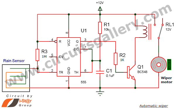
Have you seen Audi, Lexus, or Ford rain-sensing wipers and wondered how they operate in these vehicles? They are controlled by sensors located at the center of the windscreen, which detect raindrops and activate the wiper motor. The functioning...
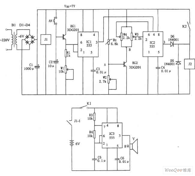
The figure illustrates the automatic watering control circuit for bean sprouts. The controller includes a step-down rectifier circuit, a power outage detection component (IC3), a timing control circuit (IC1), and a temperature control circuit (IC2). The step-down rectifier circuit...
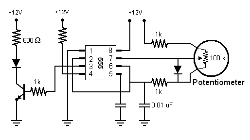
The 555 timer chip can be utilized to generate Pulse Width Modulation (PWM) signals, which can control the brightness of an LED. In a specific setup, an additional diode was incorporated to separate the charging and discharging processes of...