
A Sensitive DIY Ultrasonic Range Sensor
The ultrasonic range finder circuit operates on the principle of time-of-flight measurement of ultrasonic waves. The circuit comprises an ATmega328 microcontroller, which generates a PWM signal to drive the ultrasonic transducer. The transducer emits ultrasonic pulses, which travel through the air and reflect off nearby objects. The reflected signals are received by the transducer, which operates in receive mode. The microcontroller measures the time interval between the transmission and reception of the pulse, allowing it to compute the distance to the object using the formula:
Distance = (Time × Speed of Sound) / 2
This calculation accounts for the round trip of the ultrasonic pulse. The choice of transducers is crucial, as their resonant frequency dictates the effective range and resolution of the measurements. The 24 kHz transducers selected for this project provide a good balance between cost and performance, capable of detecting objects at distances exceeding 20 feet.
The design also incorporates a bridged output configuration to maximize the voltage supplied to the transducer. This configuration effectively doubles the output voltage, enhancing the range and sensitivity of the sensor. The transistors used in the circuit must be rated for the increased voltage levels to prevent overheating and ensure reliable operation. The overall layout of the circuit is designed to minimize interference from reflected ultrasonic waves, with careful placement of components to optimize performance.
The software driving the ultrasonic range finder is critical to ensure precise timing and control of the transducer. Adjustments to the pre-scalar settings allow for fine-tuning of the output frequency, which is essential for accurate distance measurement. The result is a cost-effective, reliable ultrasonic range finder suitable for various applications in robotics, automation, and distance measurement tasks.Some ultrasonic range finders for my project. But most of the commercial sensors like Parallax`s PING sensor and other similar products are quite expensive, especially if multiple units are needed. So I thought why not building it myself The theory behind ultrasonic ranging is quite simple. Typically a short ultrasonic burst is transmitted from the transmitter. When there is an object in the path of the ultrasonic pulse, some portion of the transmitted ultrasonic wave is reflected and the ultrasonic receiver can detect such echo. By measuring the elapsed time between the sending and the receiving of the signal along with the knowledge of the speed of sound in the medium, the distance between the receiver and the object can be calculated.
The picture below (source: Wikipedia ) illustrates this basic principal: In my design, I used separate transducers for transmitter and receiver. It is possible to multiplex the transmission and receiving with a single transducer (e. g. Maxbotix range finders ), but the design would be significantly more complex. There are quite a few ultrasonic transducers to choose from, and the main criteria are the resonant frequency, radiation pattern and sensitivity.
Generally speaking, these parameters affect the measurement in the following ways: a higher resonant frequency can provide finer details of the surroundings due to the shorter wavelength. A more directional radiation pattern can also enhance the resolution of the measurement. Sensitivity affects the efficiency of the transducer and also attributes to the SNR (signal to noise ratio).
I bought these 24 kHz transducers on sale (see picture below). These transducers are very inexpensive (around a dollar each, and even cheaper when on sale) but effective. With properly designed circuits these sensors can easily achieve a range of more than 20 feet. Of course, using the higher priced 40 kHz sensors should achieve even better performance. But for these DIY ultrasonic range finders, the choice of the transducers are really not that critical and this transducer really hits the performance to price sweet spot.
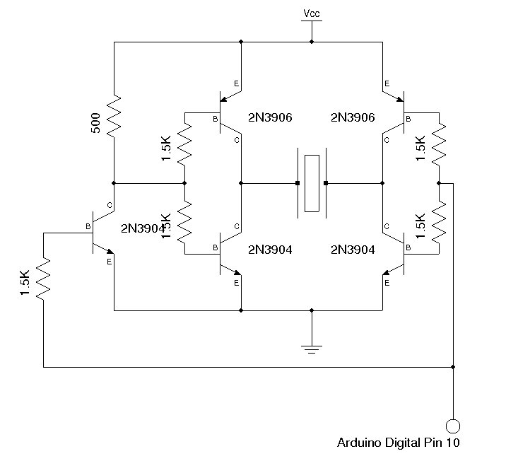
The ultrasonic transmitter is powered from ATmega328 ²s counter 1 PWM output (chip pin 16 and Arduino digital pin 10). In order to achieve the maximum output power of the transducer for a given supply voltage, I used the bridged output design as shown in the following schematics: This bridged circuit produces an output voltage roughly twice the Vcc.
I used +5V for Vcc and the result is already quite good (more than 20 feet of range). For even longer range measurement, you can safely increase this driving voltage to around 12 Volts as most ultrasonic transducers can be driven with voltage as high as 20 to 30 volts. If you increase the voltage significantly above 5V however, you will have to change the transistors to allow more power dissipation.
With 2N3904 and 2N3906 the transistors get warm during normal operation and would heat up drastically with voltage above 6V. The small ladders at the half-way voltage point in the output waveform is due to the slight added delay of the inverted signal stage due to the use of an extra NPN transistor.
To obtain purer rectangular wave form and reduce switching loss, a PNP transistor with similar timing parameters can be used on the side that is directly connected to the driving signal. For this application though, the waveform is more than adequate and the added switching loss is negligible.
In order to reduce possible interference from the reflected ultrasonic waves, the components are mounted on the reverse side of the board (below is the H-bridge circuit that drives the ultrasonic transducer, a few decoupling capacitors are used to reduce noise and they are not shown in the schematics above): The code to drive the transducer is similar to that I used previously, except that I changed the pre-scalar to 1 so that the output frequency 🔗 External reference
Related Circuits
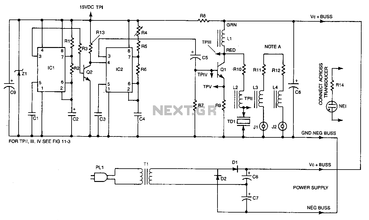
IC2 is a stable oscillator whose frequency and pulse width are determined by the values of R4, R5, R6, and C4. R4 is adjustable for precise frequency setting. The output from IC2 is at pin 3, which is capacitively...
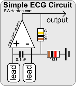
The purpose of an electrocardiograph (ECG) is to amplify, measure, and record the natural electrical potential generated by the heart. It is important to note that cardiac electrical signals are distinct from heart sounds, which are detected using a...
A few years ago, a diode-sensor based RF power meter was built using a 68HC11 microprocessor. Prior to that, an analog RF power meter with a thermal power sensor was developed. The datasheets for logarithmic amplifiers, which promised a...
This oscillator generates low-distortion sine waves within a frequency range of 16 to 22,000 Hz. The sine wave oscillator is designed to produce high-quality sine wave outputs with minimal distortion across a wide frequency spectrum. The operational range of 16...
Fans can be controlled remotely with a switch that allows for speed adjustments, and this remote control can also be integrated with other household switches. Its primary feature is the use of a sub-transmission ultrasonic transmitter, which operates without...
This tremolo effect circuit utilizes the XR2206 and the TCA730 integrated circuits, which are designed as an electronic balance and volume regulator with frequency correction. The tremolo effect circuit operates by modulating the amplitude of an audio signal, creating a...
Warning: include(partials/cookie-banner.php): Failed to open stream: Permission denied in /var/www/html/nextgr/view-circuit.php on line 713
Warning: include(): Failed opening 'partials/cookie-banner.php' for inclusion (include_path='.:/usr/share/php') in /var/www/html/nextgr/view-circuit.php on line 713