
A simple three-way speaker crossover circuit diagram
The three-way speaker crossover circuit is an essential component in audio systems, designed to separate audio signals into three distinct frequency bands: low frequencies (bass), mid frequencies (mids), and high frequencies (treble). This division is crucial for optimizing the performance of each speaker unit, as different drivers are engineered to operate efficiently within specific frequency ranges.
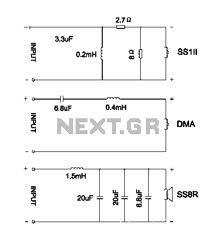
The circuit typically consists of three filters: a low-pass filter for the woofer, a bandpass filter for the midrange speaker, and a high-pass filter for the tweeter. The low-pass filter allows frequencies below a certain cutoff frequency to pass through while attenuating higher frequencies. The bandpass filter permits a specific range of frequencies to reach the midrange driver, while the high-pass filter ensures that only high-frequency signals are sent to the tweeter.
In a practical implementation, the low-pass filter can be designed using an inductor in series with the woofer and a capacitor in parallel, creating a second-order filter that effectively reduces unwanted high-frequency signals. The bandpass filter for the midrange can be constructed using a combination of capacitors and inductors to define the desired frequency range. The high-pass filter, similarly, uses a capacitor in series with the tweeter to block lower frequencies.
The crossover point, which determines the frequency at which the signal is divided, is critical and must be chosen based on the specifications of the drivers being used. Properly designed crossover networks ensure that each driver receives the appropriate frequency range, minimizing distortion and maximizing sound quality.
Overall, the three-way speaker crossover circuit is a sophisticated solution that enables a balanced and high-fidelity audio output, enhancing the listening experience by ensuring that each frequency range is handled by the most suitable driver. This careful engineering allows for a cohesive sound stage, where high, mid, and low frequencies blend seamlessly, resulting in a rich and immersive audio experience.Divider is the speaker of the brain, is crucial to the sound quality is good or bad. Music amplifier output signal must divider wave filter element processing, so that each uni t by a specific frequency signal. To scientific and rational, rigorously designed speaker of the divider, in order to effectively modify different properties speaker unit, optimized combination of such units weaknesses, vividly play their proper potential so that the frequency response of the band becomes too smooth, accurate panning phase, in order to make high, middle and bass music play out structured, co-production, clear, comfortable, broad, natural sound quality. Speaker crossover is a combined filter, an audio signal can be divided into several frequency bands. Road audio divider is made of a high-pass filter and a low-pass filter, and the three-way division has added a bandpass filter.
Described in this article is a simple three-way speaker crossover circuit diagram, inputs can be connected to the same output. as the picture shows.
Related Circuits
Streetwear trench pipe installation commonly utilizes concealed wiring methods. The control section is installed at the front door or in a centralized control room, managed by a duty electrician. The street factory area is illustrated in a figure. This...
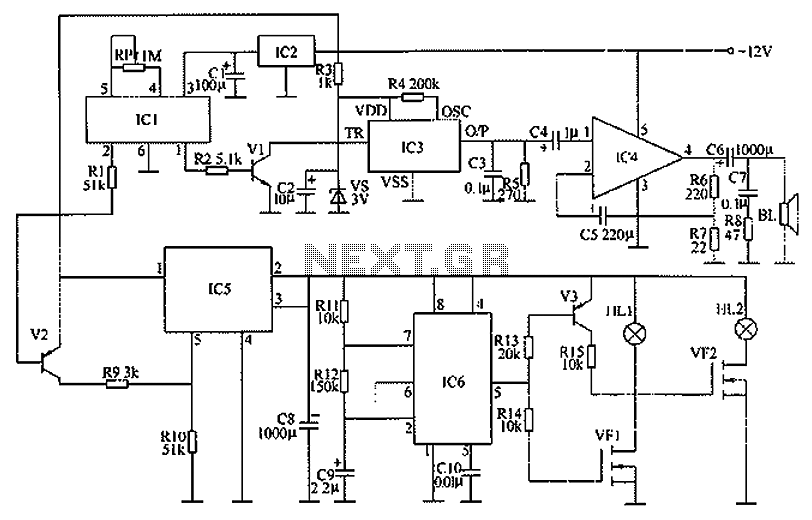
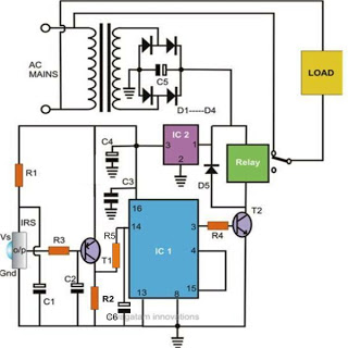
The circuit functions as a danger zone warning system incorporating a regulator circuit, a pyroelectric infrared detection trigger circuit, an electronic switching circuit, and audio circuits. The regulator circuit includes a three-terminal regulator integrated circuit (IC2), a resistor (R3),...
This 1 channel infrared transmitter/receiver remote control is the cheapest and simplest you can find. The transmitter transmits a sequence of pulses on 36 KHz frequency carrier. The diodes are Schottky type because of their low voltage drop (only...
Controlling household electrical gadgets or any electrical equipment remotely can be enjoyable. While using a remote to control devices like a TV or DVD player is a common experience, managing other domestic appliances such as water pumps and lights...
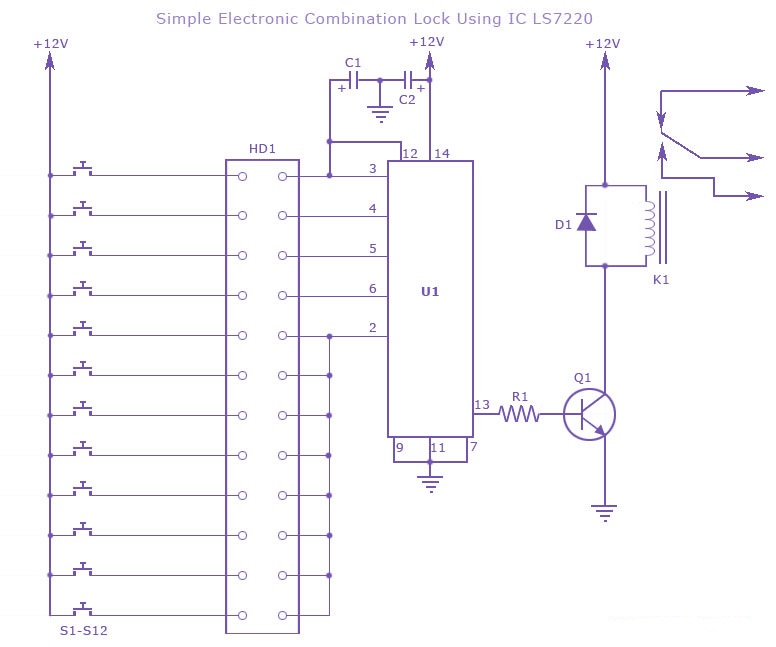
A simple electronic combination lock using the IC LS7220. This circuit employs a relay to control any device when a combination of four digits is entered. Keypads serve as the input method for entering the digits, and the correct...

The thermistor RT, along with resistors R1, R2, R3, and variable resistor RP1, creates a temperature measurement bridge. At a temperature of 20°C, the configuration of R1, R3, and the adjustment of RP1 enables the bridge to maintain balance....