
Four-Digit Keypad-Operated Switch
The circuit operates on a straightforward principle, utilizing a keypad interface to control the state of a relay. The relay serves as an output mechanism for various applications, such as alarm systems or general-purpose switching tasks.
The circuit's design emphasizes safety and flexibility, allowing for different relay configurations based on the specific requirements of the application. The SPCO or SPDT relay configuration provides a reliable switching mechanism, while the option to use a multi-pole relay enhances the circuit's adaptability.
The implementation of a complementary latch using Q5 and Q6 ensures that the relay remains activated without continuous keypresses, providing a user-friendly interface. The requirement for pressing keys "A", "B", "C", and "D" in the correct order to deactivate the relay introduces a layer of security, preventing accidental deactivation and ensuring that only authorized users can control the relay.
The design also incorporates error handling through the feedback mechanism involving Q3, which monitors for incorrect key presses. This feature enhances the reliability of the system, ensuring that users are informed of any mistakes in the code entry process.
For applications requiring higher security, the use of a larger keypad with more keys wired to terminal "F" can significantly increase the number of possible codes, making unauthorized access more difficult. The circuit's scalability and adaptability make it suitable for a wide range of applications, from simple alarm systems to more complex control mechanisms in various electronic projects.
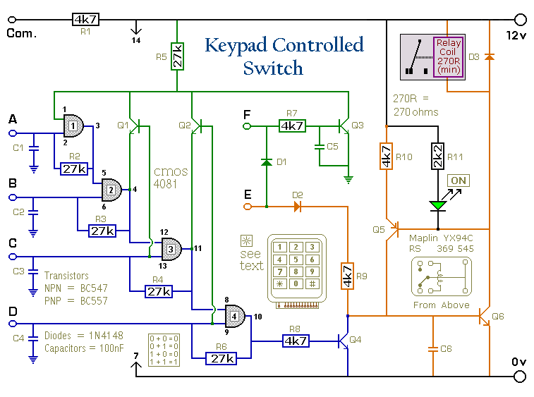
Overall, this Four-Digit Alarm Keypad circuit represents a versatile and secure solution for controlling relay operations while maintaining ease of use and adaptability for different applications.This is a universal version of the Four-Digit Alarm Keypad. I`ve modified the design of the output section - to free up the relay contacts. This allows the circuit to operate as a general-purpose switch. I used a SPCO/SPDT relay - but you can use a multi-pole relay if it suits your application. Do not use the "on-board" relay to switch mains volt age. The board`s layout does not offer sufficient isolation between the relay contacts and the low-voltage components. If you want to switch mains voltage - mount a suitably rated relay somewhere safe - Away From The Board.
The relay is energized by pressing a single key. Choose the key you want to use - and connect it to terminal "E". Choose the four keys you want to use to de-energize the relay - and connect them to "A B C & D". Wire the common to R1 and all the remaining keys to "F". The Circuit is easy to use. When you press "E" - current through D2 & R9 turns Q6 on - and energizes the relay. The two transistors - Q5 & Q6 - form a "Complementary Latch". So - when you release the key - the relay will remain energized. To de-energize the relay - you need to press keys "A B C & D" in the right order. When you do so - pin 10 of the IC goes high - and it turns Q4 on through R8. Q4 connects the base of Q6 to ground. This unlatches the complementary pair - and the relay drops out. Any keys not wired to "A B C D & E" are connected to the base of Q3 by R7. Whenever one of these "Wrong" keys is pressed - Q3 takes pin 1 low and the code entry sequence fails. If "C" or "D" is pressed out of sequence - Q1 or Q2 will also take pin 1 low - with the same result. If you make a mistake while entering the code - simply start again. The Keypad must be the kind with a common terminal and a separate connection for each key. On a 12-key pad - look for 13 terminals. The MATRIX TYPE with 7 or 8 terminals WILL NOT WORK. With a 12-key pad - over 10 000 different codes are available. If you need a more secure code - use a bigger keypad with more "Wrong" keys wired to "F". A 16-key pad gives over 40 000 different codes. The Support Material for this circuit includes a step-by-step guide to the construction of the circuit board, a parts list, a detailed circuit description and more.
🔗 External reference
Related Circuits
Light Switch. This is a light switch or light-activated relay circuit. The relay activates when the light-dependent resistor (LDR) is uncovered and deactivates when the LDR is covered. It is adjustable for sensitivity and includes an LED indicator. This light-activated...
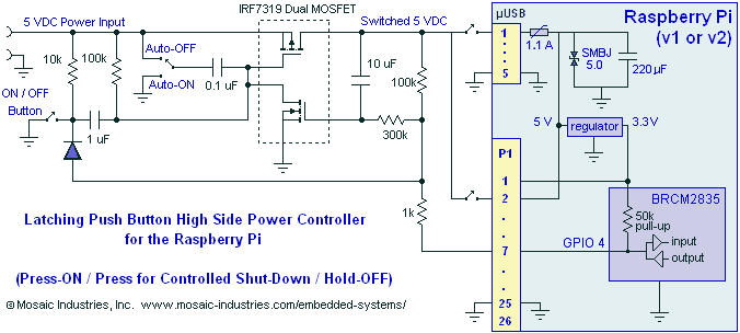
A momentary contact push button switch can be utilized to conveniently turn the Raspberry Pi (RPi) ON and OFF. Pressing the button will apply power to the micro USB header, maintaining power while the Raspberry Pi initializes and starts...
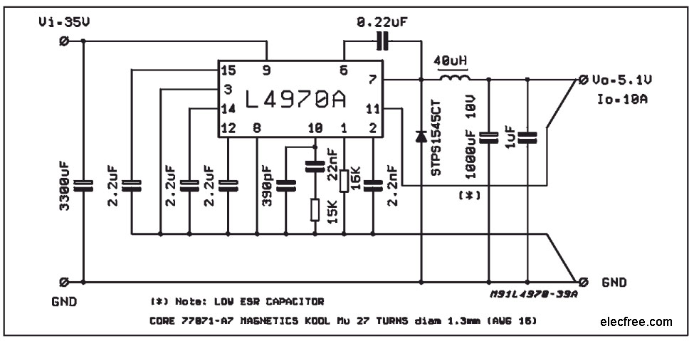
A compact and easy-to-build 5V 10A power supply circuit is sought. This circuit utilizes the L4970A IC as a 10A switching regulator. It is designed to be straightforward, serving as an example of an integrated ready-made circuit. An important...
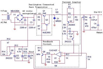
The switching power supply provides 12 volts at a maximum of 10 amps, utilizing a discrete transistor regulator with an operational amplifier acting as a comparator in the feedback circuit. The schematic does not depict the front panel power-on...
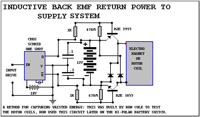
The starting point for the experiments was a switching device constructed by John Bedini for the Tesla Symposium. The objective was to enhance this switching device for compatibility with standard car or motorcycle batteries. The switching device designed by John...
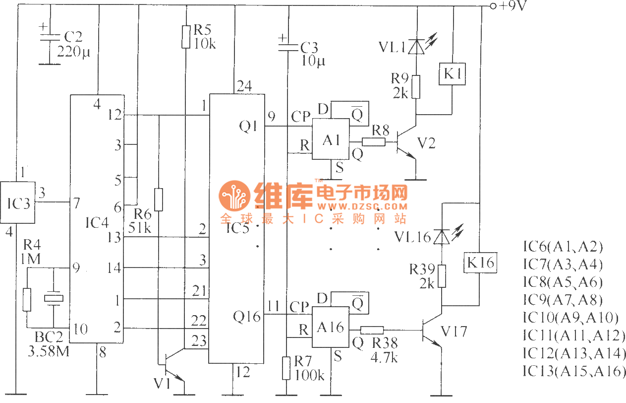
The wireless remote control transmitter circuit consists of control buttons S1 to S16, resistors R1 to R3, a capacitor C1, a regulator diode VS, a crystal oscillator BC1, and DTMF encoder integrated circuits IC1 and IC2. The circuit components...
Warning: include(partials/cookie-banner.php): Failed to open stream: Permission denied in /var/www/html/nextgr/view-circuit.php on line 713
Warning: include(): Failed opening 'partials/cookie-banner.php' for inclusion (include_path='.:/usr/share/php') in /var/www/html/nextgr/view-circuit.php on line 713