
A small generator and network control circuit
The described circuit functions as a control mechanism for a two-phase AC generator connected to a grid. It employs a Buck converter to manage voltage levels, ensuring that the output remains stable and within operational limits. The comparative analysis between sampled voltages at various pins is crucial for maintaining synchronization with the grid. The use of reference voltages allows for precise control of when the output transitions between states, facilitating the generator's connection to the grid.
The circuit's design incorporates safety features, such as the delay mechanisms that prevent premature activation during transient conditions. This ensures that the generator only connects to the grid when all parameters are within acceptable ranges, thus protecting both the generator and the grid infrastructure from potential damage due to mismatched electrical characteristics.
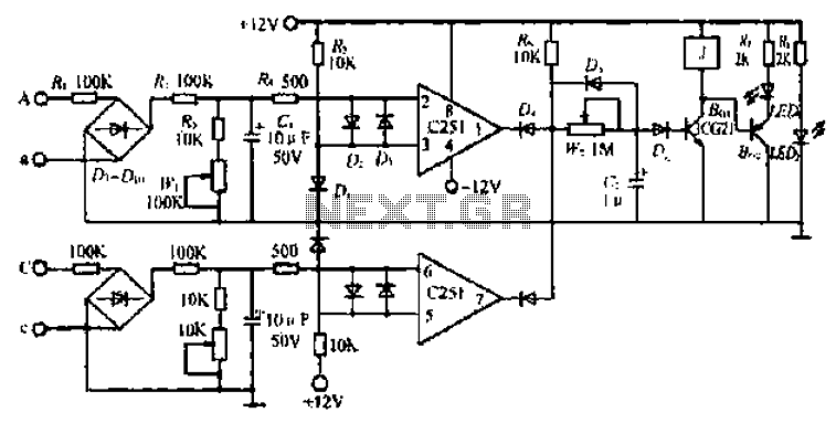
In addition, the LED indicator serves as a visual feedback mechanism, confirming the operational status of the circuit. The inclusion of diodes for rapid discharge indicates a design consideration for managing transient voltages, which can occur during switching operations. Overall, this circuit exemplifies a well-engineered approach to integrating renewable energy sources into existing electrical grids, emphasizing reliability and safety. Circle i {JA, C two-phase grid connection line. a. c technology turbine shed two lines. A, a voltage between Ri by Buck, convex - Diu chain flow. R., R3. wl dividing aftercrop sampled level lK, C. Voltages c ask the same. We know that the three-phase alternating current generator set voltage, frequency, phase sequence must be the same grid to grid, if Aa. CclbJ voltage zero crossing, then the well pattern oval foot, l asked longer the ugly zero crossing, said the frequency of the grid voltage frequency voltage generator sets out closer, the more this town by the clock network.
Aa branch voltage sampled evacuation C251 (2) feet, and its (3) pin voltage is compared, (3) pin reference voltage is 0.6V. When (2) high-voltage pin F 0.6V. (i) pin output -12v, C2 through Ds, D4 rapid discharge. BGi. 8G2 cut i1.. : When (2) pin voltage is lower than 0.6V, (1) pin + J2V. Cc branch works with Aa branch with the same. When C251 (I) of the foot and (7) feet while high I2V, the power the wind,% c for charging, delay delayed after a certain time.
BGi, BG: conduction, J action, the AC contactor units, just to complete the work well, with the lighting issue when LEDi Well claws.. Delay action means that the sampling circuit voltage is too Bong Lang zero duration to meet the requirements.
If the sampled voltage is instantaneous asked double zero or zero-crossing duration is very short. Review just called to say conditions are not met. Cz electric charge a small amount and then immediately discharge, BGi not be turned on, and therefore can not network. Tone bamboo W2 make J a one second delay action to 0.5. FIG towel CI make Hj is anti Jt sampled voltage over zero when Q is too short circuit malfunction. (Jia-wen)
Related Circuits
At some point, one may have encountered the function generator in a laboratory setting. By simply adjusting the waveform selector knob, a triangle, square, or sine wave is generated at the output. Another knob allows for the frequency of...
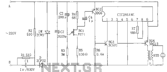
The rice cooker notification circuit operates as follows: When the rice cooker is in operation, both terminals A and B have a voltage of 0, meaning the entire circuit remains inactive. In the event that the rice cooker runs...
The electric car remote control circuit diagram enables the model car to move forward and backward, as well as turn left and right. It is simple and easy to operate. The radio remote control receiver demodulation circuit utilizes TWH9238...
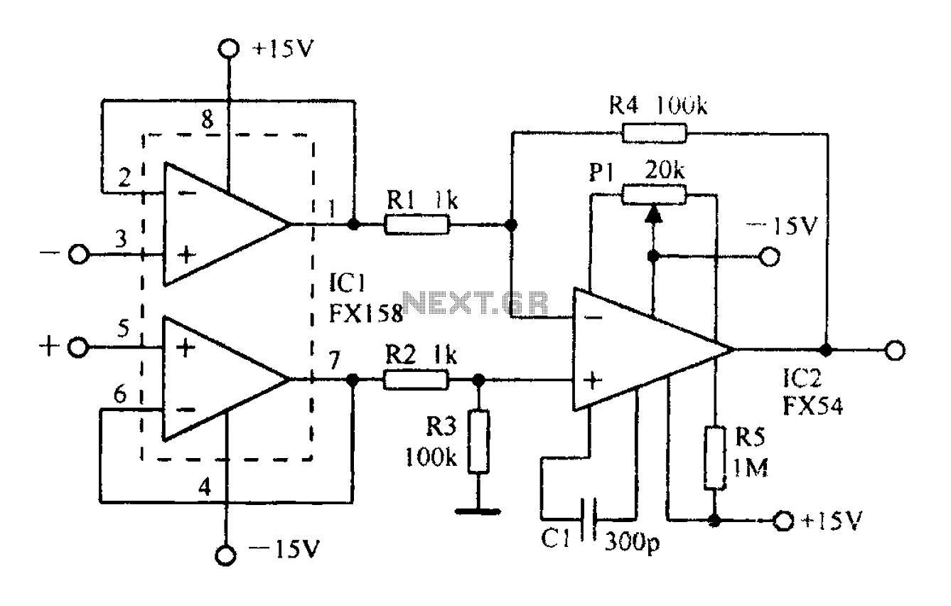
A differential amplifier with input impedance as indicated in the circuit diagram. A differential amplifier is a crucial component in various electronic applications, primarily used to amplify the difference between two input voltages while rejecting any common-mode signals. This characteristic...
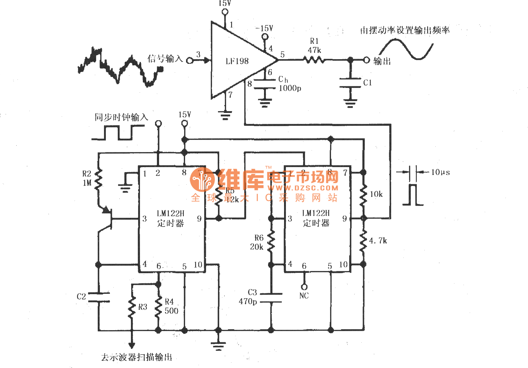
A synchronous clock signal is fed into a cascade of timer circuits composed of two LM122H devices. The synchronization clock is then converted into a pulse of the desired width, which is added to the LF198 logic end (pin...
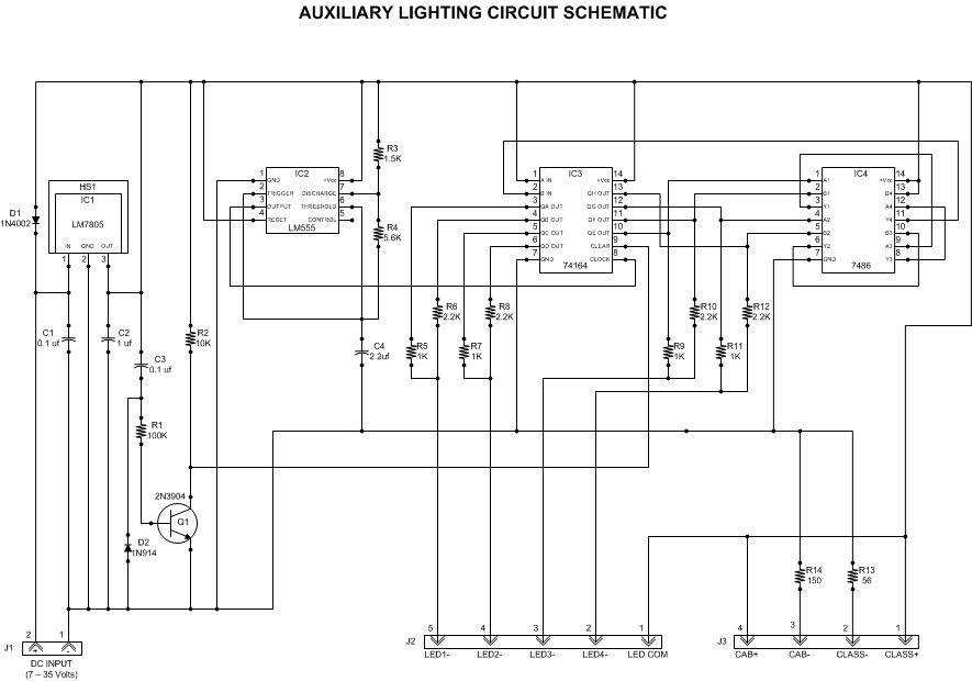
This article outlines a lighting circuit designed to create a glowing firebox effect while providing constant illumination for classification lamps and an interior cab light. It includes comprehensive information necessary for constructing the circuit, such as a detailed schematic,...