
A Solid State Photodiode Gamma Radiation Detector
Photodiodes are semiconductor devices that generate a photocurrent when exposed to light. In the context of gamma photon detection, the photodiode must be carefully selected to ensure it has a suitable response to the high-energy photons. The circuit typically includes a reverse-biased photodiode connected to an amplifier, which is crucial for enhancing the weak photocurrent generated by the photodiode.
The design of the photodiode detector takes into account several factors, including the choice of photodiode material, the operating wavelength range, and the necessary shielding to prevent interference from background light and other radiation. Common materials for photodiodes include silicon and germanium, with each having its advantages depending on the gamma energy levels being detected.
The amplification stage is often achieved using operational amplifiers (op-amps) configured in a transimpedance amplifier arrangement. This configuration converts the photocurrent into a measurable voltage output. The gain of the amplifier must be set accurately, as it directly influences the sensitivity and noise performance of the detector. Component values, such as feedback resistors and capacitors, are critical; they must be chosen based on the expected range of gamma photon energies and the desired bandwidth of the detection system.
In addition to the photodiode and amplifier, the circuit may include additional components such as filters to eliminate noise, biasing circuits to stabilize the photodiode operation, and output stages to interface with data acquisition systems. The layout of the circuit is also important; proper grounding and shielding techniques must be employed to minimize electromagnetic interference, which can significantly affect the performance of the detector.
Overall, while the basic operation of a photodiode is straightforward, the nuances of designing a detector for gamma photons require careful attention to detail and component selection to achieve reliable and accurate measurement.Photodiodes convert light into current and this current can be coverted into voltage and amplified. Sounds simple right? Well, when trying to detect Gamma photons, the design of a photodiode detector is not so simple. This circuit is not paticularly complicated, but the design took some effort and many of the component values are critical. Image of unshielded detector Schematic. 🔗 External reference
Related Circuits
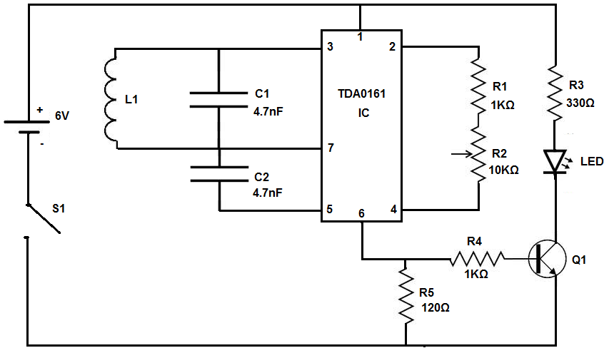
This circuit will detect AC line currents of about 250 mA or more without making any electrical connections to the line. Current is detected by passing one of the AC lines through an inductive pickup (L1) made with a...
Ions are defined as electrically charged atoms. Positively charged ions have a deficiency of electrons, and negatively charged ions have a surplus of electrons. An ion can also be classified as an atom or molecule with an electrostatic charge....
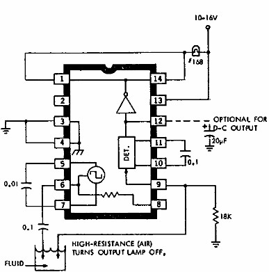
This electronic liquid detector circuit diagram utilizes the ULN2429A monolithic bipolar integrated circuit, which is designed to detect the presence or absence of various types of liquids. The detection mechanism involves comparing the resistance of a probe immersed in...
This circuit employs a 1458 dual op-amp to create a radar detector. C1 acts as the radar signal detector. The first op-amp functions as a current-to-voltage converter, while the second op-amp buffers the output to drive the piezo transducer....
The device being constructed will serve as a metal detector, capable of locating metal objects such as coins, nails, and keys, including car keys that may be misplaced. It can also detect gold, although it may not possess industrial...
The continuity tester can distinguish between high, medium, and low-resistance connections. When there is a conductive path between the inputs, connected to small probes, a current flows from the +9 V line to ground through resistors R1 and R2....