
Experiments with coupled circuits
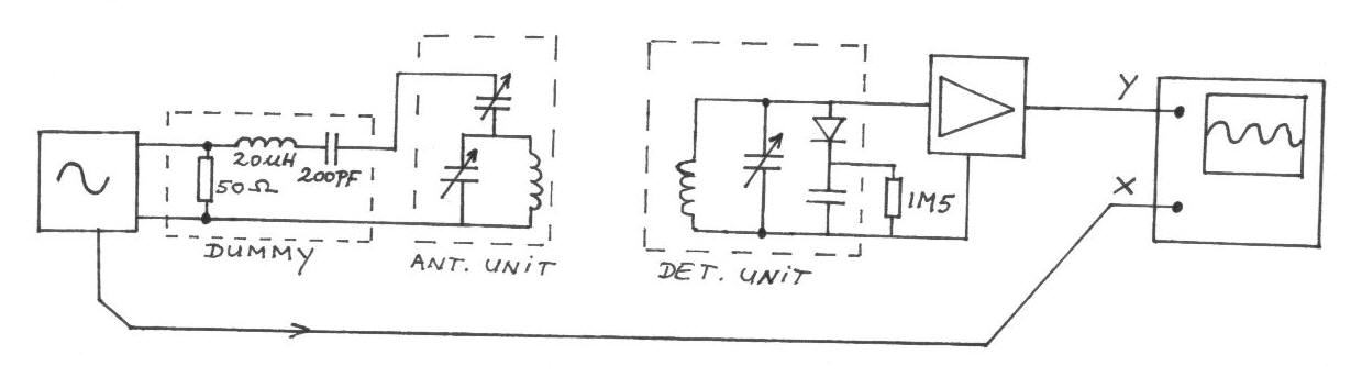
The described circuit operates by maintaining a stable frequency that alternates between two specific values. This frequency modulation allows for the analysis of the response characteristics of two distinct circuits when visualized on an oscilloscope. The oscilloscope serves as a crucial tool in this setup, providing a visual representation of the frequency spectrum, which includes the amplitude and phase response of the circuits under test.
The receiver circuit is designed to accept a low input voltage of 0.1 Volt peak-to-peak. This low-level signal is processed and amplified by the subsequent stages of the circuit. The detector circuit, which follows the receiver, is responsible for further processing the signal. It successfully amplifies the input voltage to approximately 5 Volts peak-to-peak. This amplification results in a voltage gain of 50 times, which is significant for applications requiring enhanced signal strength for further analysis or transmission.
The design of the circuit may involve various electronic components, such as operational amplifiers for amplification, resistors for setting gain levels, and capacitors for filtering out unwanted frequencies. Proper selection of these components is essential to ensure that the circuit operates efficiently within the desired frequency range while minimizing distortion and noise.
In practical applications, this type of circuit could be utilized in communication systems, signal processing, or instrumentation, where accurate frequency response measurements are critical. The ability to visualize the response curves on an oscilloscope allows engineers to assess the performance of the circuits and make necessary adjustments to optimize their functionality.The frequency is constant varying between two set values, on the oscilloscope screen you get a frequency spectrum with the response curve of the two circuits. The input voltage of the receiver is 0. 1 Volt peak-peak, the voltage across the detector circuit is about 5 Volt peak-peak, so we have a voltage gain of 50 times.
🔗 External reference
Related Circuits
This is a diagram of a car audio active loudspeaker utilizing the LF353 operational amplifier from National Semiconductor. For optimal performance, the NE5532 is recommended to split the audio signal into three frequency bands using an active filter. The...
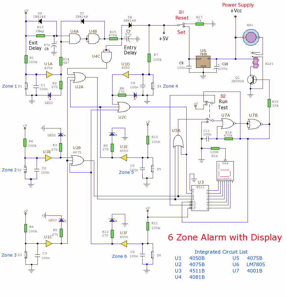
This section includes intruder alarms for homes, cars, and motorcycles, as well as power failure alarms, water level alarms, and a snore detector. All circuits are organized alphabetically on the Circuit Index page and chronologically on the update page....
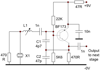
This circuit operates effectively from low frequencies up to at least 120 MHz using series resonant crystals in their fundamental or overtone mode. The output can be obtained from the feedback tap, a low impedance winding on L2, or...
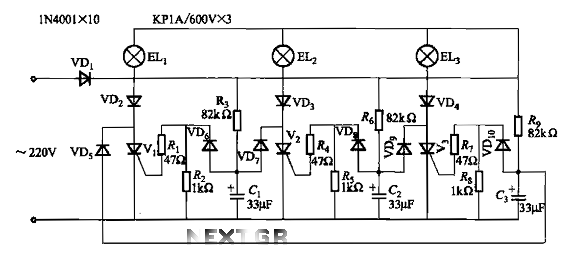
The circuit operates with a 220V mains supply through a diode (VDi) configured as a half-wave rectifier. Capacitors C1 to C3 are charged, and due to the lack of full synchronization in the charging process, a pilot thyristor is...
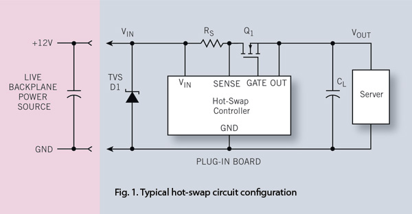
To ensure reliability, the server system designer must take into account the parasitics of hot-swap circuits and their associated transient behavior. It is recommended that a transient voltage suppressor (TVS) diode clamp be utilized at the line card input....
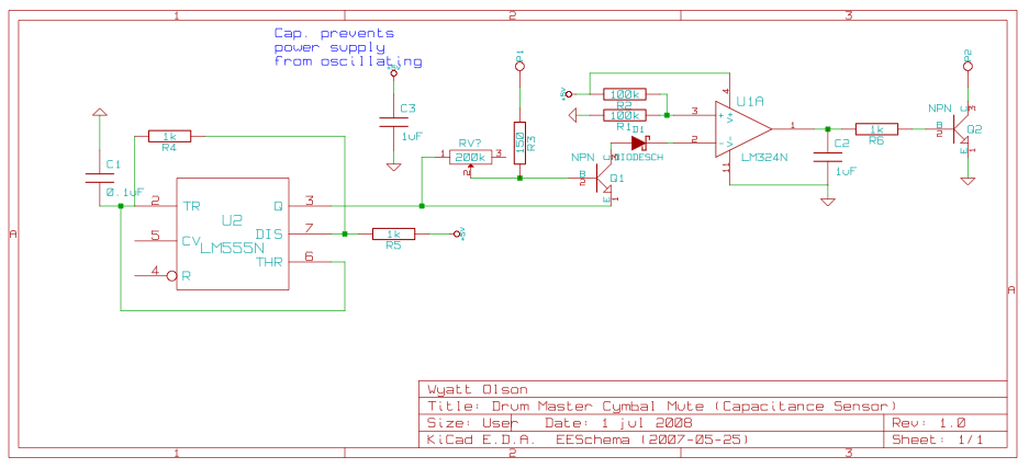
This page contains various small circuits created over time. Some circuits are trivial, while others are more complex, but all are intended to be useful for a variety of projects. Most include both the schematics and the source (KiCad)...
Warning: include(partials/cookie-banner.php): Failed to open stream: Permission denied in /var/www/html/nextgr/view-circuit.php on line 713
Warning: include(): Failed opening 'partials/cookie-banner.php' for inclusion (include_path='.:/usr/share/php') in /var/www/html/nextgr/view-circuit.php on line 713