
A Treacle Tin Radiation Detector

The ionization chamber radiation detector operates on the principle of measuring ionization events caused by radiation interacting with air molecules within the chamber. The design leverages an air-filled vessel, typically cylindrical, which is open at one end to allow radiation to enter. The ionization process begins when alpha, beta, or gamma radiation passes through the chamber, resulting in the ejection of electrons from air molecules. This creates positive ions and free electrons, which are then attracted to the electrodes positioned at opposite ends of the chamber.
In this prototype, the treacle tin serves as both the chamber and the outer electrode, while the central electrode is a thick copper wire. The choice of materials is critical, particularly due to the minuscule currents generated during operation, which typically range in the nanoamp to picoamp scale. High-quality insulation is paramount; therefore, the wire is introduced through a PTFE bush, ensuring that electrical leakage is minimized. The insulation provided by PTFE is effective, allowing the detector to maintain accuracy in measurements.
To amplify the tiny currents produced, a PN4117 JFET is employed, which is known for its low noise characteristics and high input impedance. This device amplifies the ionization current to a measurable level, which is then processed by an analog-to-digital converter (ADC) integrated within the microcontroller. The use of a screened enclosure for the amplifier further reduces interference from external electrical noise, ensuring that the readings are as accurate as possible.
The Nanode microcontroller, with its integrated Ethernet capability, is designed for ease of DIY assembly, making it an ideal choice for such projects. The ability to log data directly to the Internet or broadcast readings wirelessly enhances the detector's functionality, allowing for real-time monitoring and data collection. In scenarios where an Ethernet connection is unavailable, the 868MHz wireless option provides an alternative means of data transmission, potentially utilizing UAV drones equipped with communication systems to relay information back to monitoring stations.
Overall, this radiation detector prototype exemplifies the innovative use of simple materials and accessible technology for the purpose of enhancing disaster response capabilities. The ongoing development and refinement of the code and hardware will contribute to the effectiveness and reliability of the device in real-world applications.The OpenRelief project is building open, modular information solutions for disaster relief , and as part of which they`re developing a range of network-enabled sensors. I offered to help out by prototyping a radiation detector, opting to use an ionisation chamber in favour of a Geiger-Muller tube and constructing this from an old treacle tin.
In this post I describe the basic principles of operation, before going on to cover early experiences and next steps. The Geiger counter has become synonymous with radiation detection but there are many ways to achieve this other than using a Geiger-Muller (GM) tube.
The ionisation chamber works on similar principles to the GM tube, but is an incredibly simple design that can be constructed from an old tin can and which does not require the use of high voltages and an inert gas and halogen fill. You don`t get something for nothing and there are trade-offs, but we`ll come to those later. The inspiration for building an ionisation chamber-based detector came last year around the time of the Fukushima Daiichi nuclear disaster.
As fears rose that insufficient information was available to track the spread of leaked radioactive materials, hackers around the world worked on designs for DIY Geiger counters, and those based in Japan made use of the Cosm (formerly Pachube) web service to publish real-time data online. As one might expect there was a run on GM tubes and supplies of those at the cheaper end of the market dried up.
Which led me to thinking: why not use an ionisation chamber instead This is essentially little more than an air filled vessel which is open at one end, and with two electrodes across which the flow of current is measured. As radiation such as alpha or beta particles or gamma rays enters the chamber it strips the electrons from air molecules, and the ions and dissociated electrons are attracted to electrodes of the opposite polarity.
Tiny currents in the order of nano/picoamps are measured flowing between the electrodes, and this provides an indication of the level of ionising radiation entering the chamber. In this prototype an empty steel treacle tin was used for the chamber and to provide an outer electrode, with a thick copper wire used for a central electrode.
Given the incredibly small currents that are being measured the use of extremely good insulating material is essential, and the wire is fed into the can through a PTFE (a. k. a. TeflonTM) bush and supported at the other end by PTFE rod. An electrometer grade PN4117 JFET is used to amplify the current in order that we might then measure this using a microcontroller ADC.
So as to reduce spurious readings the amplifier is screened in its own enclosure. The PTFE bushes that lead the wires out from the diecast aluminium box are not strictly necessary as insulation requirements are not as demanding after the JFET. The ionisation chamber assembly is connected to a Nanode ” an Arduino-compatible microcontroller that makes use of through-hole components (for ease of DIY assembly) and integrates Ethernet, along with optional extras of 868MHz wireless, an RTC and microSD.
The idea being that the detector can log data directly to the Internet if an Ethernet connection is available, or alternatively it may broadcast readings via 868MHz wireless. In the case of the latter there would either be ground-based wireless infrastructure, or UAV drones flying overhead that have wireless and a GSM/3G modem or some other means of relaying data to monitoring stations.
For those that are curious the code can be found at GitHub, but please note that at the time of writing this is alpha quality and it`s very much a work in progress. At this point I must give due credit to Charles Wenzel, who not only published the design that I`ve made use of here, but has also been extremely generous with his time in providing advice.
One of the really great thing about his approach is that, a 🔗 External reference
Related Circuits

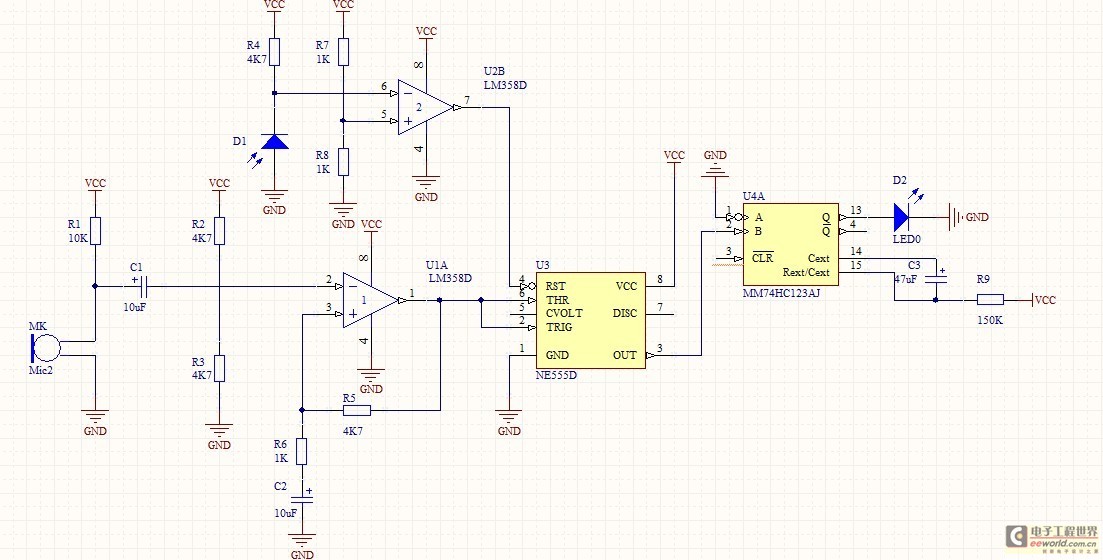
This is a simple RF bug detector designed to identify spy bugs, capable of operating up to 2 GHz. Below are some essential components required for this circuit. The RF bug detector circuit functions by utilizing radio frequency signals...
The optically-controlled circuit plays a crucial role in urban street lighting and corridor illumination. By utilizing this circuit, lighting lamps can be automatically turned on and off based on ambient light levels, thereby reducing the need for manual control,...
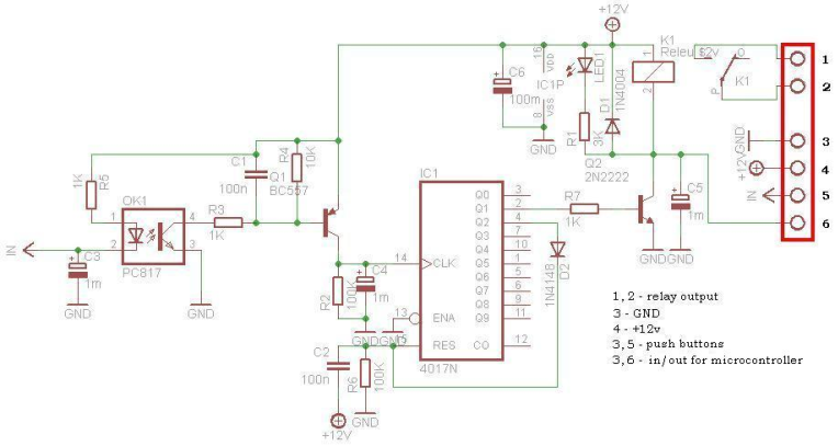
This circuit is operating the room illuminates. The basic component of the circuit is a IC1 (CD4017). Push buttons room are connected by normally wired to the circuit. All circuit is separately by optocoupler, which means that the circuit...
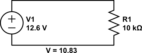
Connect a 12V fan to this circuit that consumes 70mA (0.07A), ensuring the circuit can supply at least that amount of current. There appears to be a misunderstanding regarding the analysis. The voltage drop across the resistor equals the...
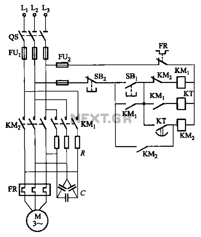
The circuit depicted in Figure 3-35 demonstrates a method for starting a motor that transitions to full voltage through a step-down switching process. This approach provides an uninterruptible power supply, effectively preventing issues related to switching currents that may...
This circuit features an appealing Christmas lights setup. Upon activation, the lights (HL) gradually increase in brightness. Once they reach maximum brightness, they automatically dim, and upon reaching the lowest brightness, they gradually brighten again, creating a smooth transition...