
A933 Transistor Telephone Listening

The A933 Transistor Telephone Listening Circuit is designed to function as a radio frequency receiver, specifically tuned to intercept signals in the FM band. The circuit utilizes the A933 transistor, which is known for its high gain and frequency response suitable for audio applications.
The schematic typically includes essential components such as resistors, capacitors, and an antenna. The tuning capability from 88 to 94 MHz allows the user to select various frequencies within the FM band, making it versatile for different transmission sources. The simple design enables ease of assembly and troubleshooting, ideal for both hobbyists and educational purposes.
In operation, the antenna captures the radio waves, which are then amplified by the A933 transistor. The circuit may also include a variable capacitor or inductor to adjust the resonant frequency, allowing for precise tuning. The output can be connected to a speaker or headphone for audio output, providing a clear reception of the signals.
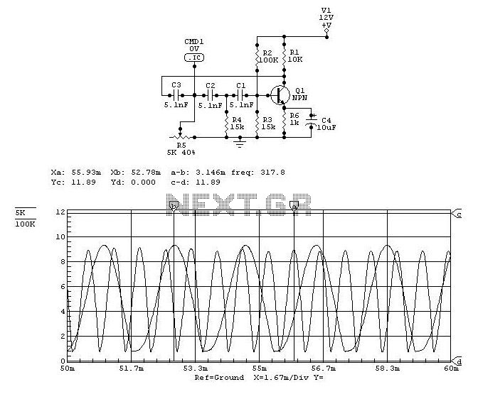
Safety considerations should be taken into account, particularly regarding the power supply and grounding of the circuit to prevent interference and ensure optimal performance. Proper shielding may also be necessary to minimize noise and enhance signal clarity.The following circuit shows about A933 Transistor Telephone Listening Circuit Diagram. Features: can be tuned from 88 to about 94Mhz, simple .. 🔗 External reference
Related Circuits
Here is a teleremote circuit which enables switching on and off of appliances through telephone lines. It can be used to switch appliances from any distance, overcoming the limited range of infrared and radio remote controls. The circuit described...
Audio can be extracted from a telephone line using a transformer and a capacitor to isolate the line from external equipment. A non-polarized capacitor is placed in series with the transformer line connection to prevent direct current from flowing...
The Link circuitry is simple and efficient, employing just two integrated circuits (ICs), a few transistors, and common components. It operates on 12 volts and is easy to assemble. This intercom system can connect various locations such as the...
The design objective was to produce an hFE tester with switched collector currents for the DUT (Device Under Test) covering a range suitable for the selection and matching of output transistors for amplifiers such as the JLH Class-A, ESP...
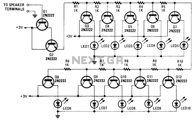
A resistor network (R1 through R10) with emitter followers (Q1 and Q2) drives LED drivers (Q3 through Q7). This circuit was utilized as a "light organ" to provide visual volume indication. It can be connected to a speaker, another...
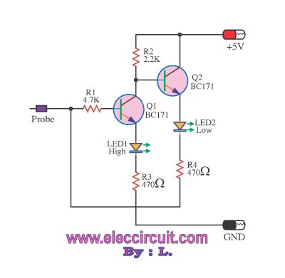
This logic probe circuit is designed for checking voltage levels in TTL circuits. It receives signals from the circuit being tested and indicates whether the logic level is high or low. When the input voltage at the probe tip...